Kia Optima DL3: Brake System / ESC (Electronic Stability Control) System
Components and components location
| Components |
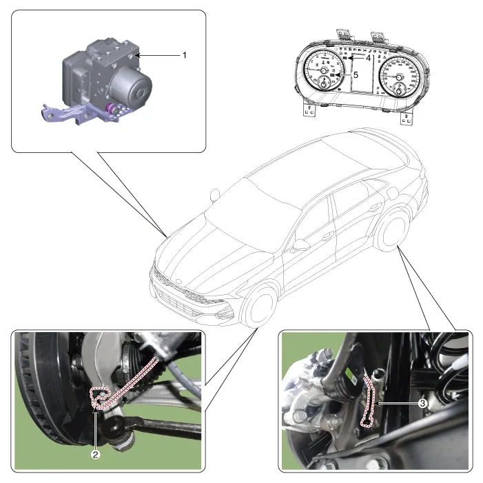
| 1. ESC control module (HECU)
2. Front wheel speed sensor 3. Rear wheel speed sensor |
4. ABS warning lamp 5. Parking brake/ EBD warning lamp |
Description and operation
| Description of ESC |
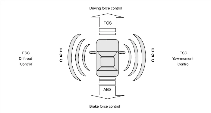
Electronic Stability Control (ESC) recognizes critical driving conditions, such as panic reactions in dangerous situations, and stabilizes the vehicle by individual wheel braking and engine control input.
ESC adds an additional function known as Active Yaw Control (AYC) to the ABS, TCS, EBD and ESC functions. On contrary, the ABS/TCS function controls wheel slip during braking and accelerating, and thus, mainly intervenes in the longitudinal dynamics of the vehicle, and the active yaw control stabilizes the vehicle on the vertical axis.
This is achieved by individual wheel brake intervention and adaptation of momentary engine torque with no need for any action to be taken by the driver.
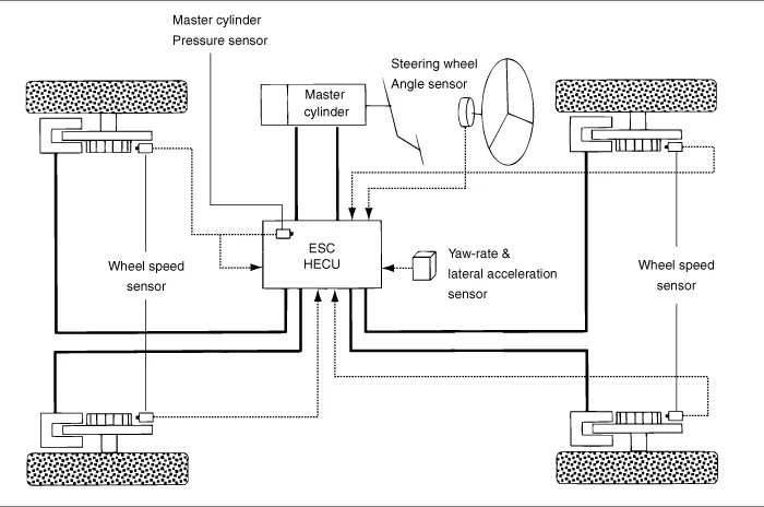
ESC essentially consists of three assemblies : the sensors, the electronic control unit and the actuators.
The stability control feature works under all driving and operating conditions. Under certain driving conditions, the ABS/TCS function can be activated simultaneously with the ESC function in response to a command by the driver.
In the event of a failure of the stability control function, the basic safety function, ABS, is still maintained.
Description of ESC Control
ESC system consists of ABS/EBD, TCS and AYC functions.
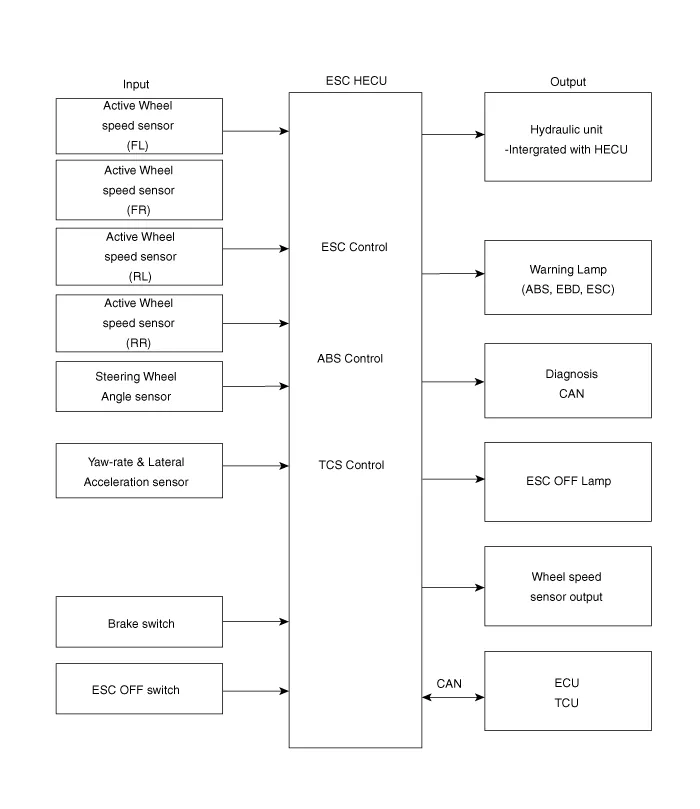
ABS/EBD function : The ECU changes the active sensor signal (current shift) coming from the four wheel sensors into square waves. By using the input of above signals, the ECU calculates the vehicle speed and the acceleration & deceleration of the four wheels. And, the ECU judges whether the ABS/EBD should be actuated or not.
TCS function prevents the wheel slip of drive direction by adding the brake pressure and engine torque reduction via CAN communication. TCS function uses the wheel speed sensor signal to determine the wheel slip as far as ABS function.
AYC function prevents unstable maneuver of the vehicle. To determine the vehicle maneuver, AYC function uses the maneuver sensor signals (Yaw Rate Sensor, Lateral Acceleration Sensor, and Steering Wheel Angle Sensor).
If vehicle maneuver is unstable (Over Steer or Under Steer), AYC function applies the brake pressure on certain wheel, and sends engine torque reduction signal by CAN.
After the key-on, the ECU continuously diagnoses the system failure (self-diagnosis). If the system failure is detected, the ECU informs driver of the system failure through the BRAKE/ABS/ESC warning lamp (fail-safe warning).
Input and Output Diagram
| ESC Operation Mode |
| ESC / ESCi |
| ESCi+ |
| 1. |
ESC Non-operation : Normal braking.
|
| 2. |
ESC operation
|
||||||||||||||||||||||
Warning Lamp Control
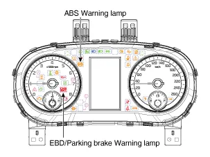
ABS Warning Lamp module
The active ABS warning lamp module indicates the self-test and failure status of the ABS. The ABS warning lamp is turned on under the following conditions:
| – |
During the initialization phase after IGN ON. (continuously 3 seconds). |
| – |
In the event of ABS function failure. |
| – |
During diagnostic mode. |
| – |
When the communication between HECU and PCM has failed. |
| – |
Cluster lamp is ON when communication is impossible with CAN module. |
EBD/Parking Brake Warning Lamp Module
The active EBD warning lamp module indicates the self-test and failure status of the EBD. However, in case the Parking Brake Switch is turned on, the EBD warning lamp is always turned on regardless of EBD functions. The EBD warning lamp is turned on under the following conditions:
| – |
During the initialization phase after IGN ON. (continuously 3 seconds). |
| – |
When the Parking Brake Switch is ON or brake fluid level is low. |
| – |
When the EBD function is out of order. |
| – |
During diagnostic mode. |
| – |
When the communication between HECU and PCM has failed. |
| – |
Cluster lamp is ON when communication is impossible with CAN module. |
ESC Function/Warning Lamp
The ESC function/warning lamp indicates the self-test and failure status of the ESC.
The ESC function/warning lamp is turned on under the following conditions:
| – |
During the initialization phase after IGN ON. (continuously 3 seconds). |
| – |
When the ESC function is inhibited by system failure. |
| – |
When the ESC control is operating. (Blinking - 2Hz) |
| – |
During diagnostic mode.(Except standard mode) |
| – |
Cluster lamp is ON when communication is impossible with CAN module. |
ESC Off Lamp
The ESC Off lamp indicates the self-test and operating status of the ESC.
The ESC Off lamp operates under the following conditions :
| – |
During the initialization mode after IGN ON. (continuously 3 seconds). |
| – |
ESC Off lamp is ON when driver turns OFF ESC switch. |
ESC On/Off Switch
The ESC On/Off Switch is used to toggle the ESC function between On/Off states based upon driver input.
The On/Off switch is a normally open, is a momentary contact switch.
Initial status of the ESC function is ON.
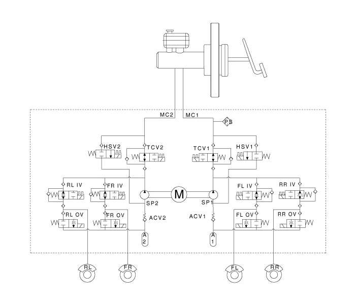
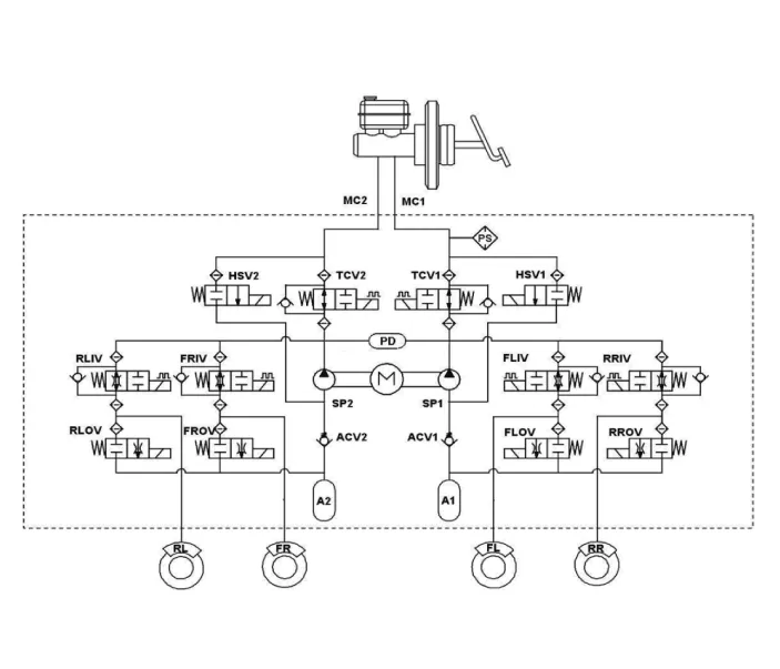
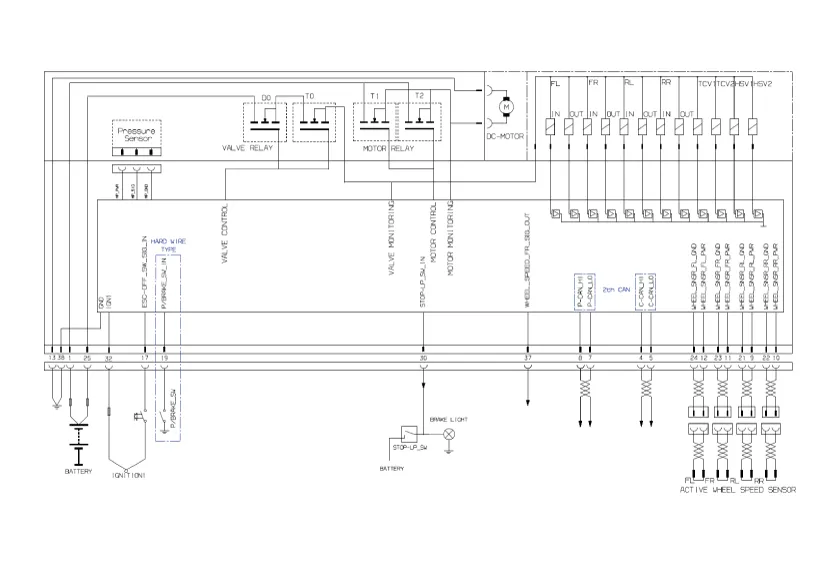
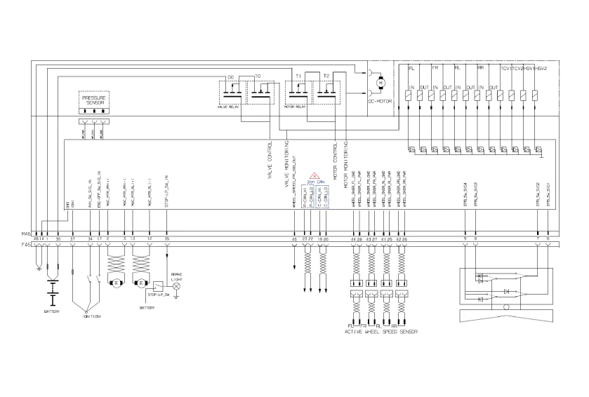
Schematic diagrams
| Circuit Diagram |
[EPB None Apply]
[EPB Apply]
| Terminal Function |
[EPB None Apply]
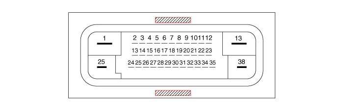
|
PIN No |
Desciption |
Current |
|
|
max |
min |
||
|
1 |
Voltage supply for pump motor |
40A |
10 MΩ |
|
2 |
Hazard switch |
1.2 mA |
250 MΩ |
|
3 |
- |
|
|
|
6 |
|
|
|
|
7 |
P-CAN LOW |
100 mA |
250 MΩ |
|
8 |
P-CAN High |
100 mA |
250 MΩ |
|
9 |
Wheel speed sensor power voltage (RL) |
100 mA |
250 MΩ |
|
10 |
Wheel speed sensor power voltage (RR) |
100 mA |
250 MΩ |
|
11 |
Wheel speed sensor power voltage (FR) |
100 mA |
250 MΩ |
|
12 |
Wheel speed sensor power voltage (FL) |
100 mA |
250 MΩ |
|
13 |
Recirculation pump ground |
40A |
10 MΩ |
|
14 |
- |
|
|
|
17 |
ESC Switch |
1.2 mA |
250 MΩ |
|
18 |
- |
|
|
|
19 |
Parking brake switch |
1.2 mA |
250 MΩ |
|
20 |
- |
|
|
|
21 |
Wheel speed sensor ground (RL) |
40 mA |
250 MΩ |
|
22 |
Wheel speed sensor ground (RR) |
40 mA |
250 MΩ |
|
23 |
Wheel speed sensor ground (FR) |
40 mA |
250 MΩ |
|
24 |
Wheel speed sensor ground (FL) |
40 mA |
250 MΩ |
|
25 |
Voltage supply for solenoid valves |
30A |
10 MΩ |
|
26 |
- |
|
|
|
27 |
- |
|
|
|
28 |
- |
|
|
|
29 |
- |
|
|
|
30 |
Brake lamp switch |
1.2 mA |
250 MΩ |
|
31 |
- |
|
|
|
32 |
IGN 1 |
10mA |
50MΩ |
|
33 |
- |
|
|
|
36 |
- |
|
|
|
37 |
Wheel speed sensor output (FR) |
50 mA |
250 MΩ |
|
38 |
Ground for solenoid valves and ECU |
30A |
10 MΩ |
[EPB Apply]
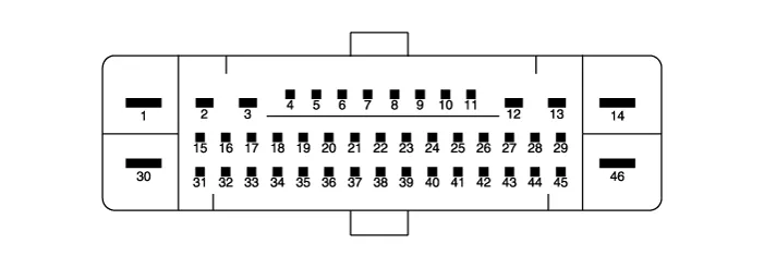
|
PIN No |
Desciption |
Current |
|
|
max |
min |
||
|
1 |
Voltage supply for pump motor |
39A |
10 MΩ |
|
2 |
RR EPB motor power |
30A |
10 MΩ |
|
3 |
RR EPB motor ground |
30A |
10 MΩ |
|
6 |
Electric parking brake signal 1 |
20 mA |
250 MΩ |
|
7 |
Electric parking brake signal 2 |
20 mA |
250 MΩ |
|
8 |
Electric parking brake signal 3 |
20 mA |
250 MΩ |
|
9 |
Electric parking brake signal 4 |
20 mA |
250 MΩ |
|
10 |
- |
- |
250 MΩ |
|
11 |
- |
- |
- |
|
12 |
RL EPB motor ground |
30A |
- |
|
13 |
RL EPB motor power |
30A |
10 MΩ |
|
14 |
Ground for solenoid valves and ECU |
30A |
10 MΩ |
|
16 |
- |
- |
250 MΩ |
|
17 |
ESP OFF switch signal |
16.8 mA |
|
|
19 |
Local CAN High |
10 mA |
250 MΩ |
|
20 |
Local CAN Low |
30 mA |
250 MΩ |
|
21 |
- |
- |
250 MΩ |
|
22 |
P-CAN LOW |
- |
|
|
23 |
P-CAN High |
200 mA |
250 MΩ |
|
24 |
- |
- |
250 MΩ |
|
25 |
Wheel speed sensor supply voltage (RL) |
16.8 mA |
|
|
26 |
Wheel speed sensor supply voltage (RR) |
16.8 mA |
250 MΩ |
|
27 |
Wheel speed sensor supply voltage (FR) |
16.8 mA |
250 MΩ |
|
28 |
Wheel speed sensor supply voltage (FL) |
- |
250 MΩ |
|
29 |
- |
16.8 mA |
250 MΩ |
|
30 |
Voltage supply for solenoid valves |
30A |
|
|
31 |
- |
- |
10 MΩ |
|
32 |
- |
Open drain |
|
|
33 |
- |
- |
|
|
34 |
Auto holding ON/OFF switch signal |
10 mA |
|
|
35 |
Brake light switch |
10 mA |
250 MΩ |
|
37 |
IGN 1 |
5A |
250 MΩ |
|
39 |
- |
16.8 mA |
250 MΩ |
|
40 |
- |
- |
|
|
41 |
- |
- |
|
|
42 |
- |
- |
250 MΩ |
|
43 |
- |
- |
250 MΩ |
|
44 |
Wheel speed sensor ground (FL) |
30 mA |
250 MΩ |
|
45 |
Wheel speed sensor ground (FR) |
30 mA |
250 MΩ |
|
46 |
Recirculation pump ground |
40A |
250 MΩ |
Troubleshooting
| Troubleshooting |
Failure Diagnosis
| 1. |
In principle, ESC and TCS controls are prohibited in case of ABS failure. |
| 2. |
When ESC or TCS fails, only the failed system control is prohibited. |
| 3. |
The solenoid valve relay should be turned off in case of ESC failure, refer to the ABS fail-safe. |
| 4. |
Information on ABS fail-safe is identical to the fail-safe in systems where ESC is not installed. |
Memory of Fail Code
| 1. |
It keeps the code as far as the backup lamp power is connected. (O) |
| 2. |
It keeps the code as far as the HCU power is on. (X) |
Failure Checkup
| 1. |
Initial checkup is performed immediately after the HECU is powered on. |
| 2. |
Valve relay checkup is performed immediately after switching "ON" the IG2. |
| 3. |
It executes the checkup all the time while the IG2 is switched "ON". |
| 4. |
Initial checkup is made in the following cases.
|
| 5. |
Check up continues even if the brake lamp is switched on. |
| 6. |
When performing ABS or ESC control before the initial checkup, stop the initial checkup and wait for the HECU power input again. |
| 7. |
Judge failure in the following cases.
|
Countermeasures in Fail
| 1. |
Turn the system down and perform the following actions and wait for HECU to power OFF. |
| 2. |
Turn the valve relay off. |
| 3. |
Stop the control during the operation and do not execute anything until it recovers to normal condition. |
Warning Lamp ON
| 1. |
ESC warning lamps turns on for 3 seconds after IGN ON. |
| 2. |
ESC function lamp blinks when ESC Act. |
| 3. |
In case of ESC failure, ESC warning lamp turns ON. |
| 4. |
ESC OFF lamp turns on: – When ESC is switched OFF –3 seconds after IGN ON |
- ESC Control Module
- ESC OFF Switch
- Front Wheel Speed Sensor
- Rear Wheel Speed Sensor
- Emergency Signal System
Description and operation Description The electronic parking brake (EPB) is different from existing parking systems which operated with the brake pedal or the lever type.
Components and components location Components 1. Front - right (FR) 2. Rear - left (RL) 3. Rear - right (RR) 4. Front - left (FL) 5.
Other information:
Kia Optima DL3 2019-2026 Service and Repair Manual: Integrated Memory Seat (IMS) Switch
Schematic diagrams Connector and Terminal Function Repair procedures Removal When prying with a flat-tip screwdriver or use a prying trim tool, wrap it with protective tape, and apply protective tape around the related parts, to prevent dam
Kia Optima DL3 2019-2026 Service and Repair Manual: Power Seat Control Switch
Repair procedures Removal 1. Remove the front seat shield outer cover. (Refer to Body - "Front Seat Shield Outer Cover") 2. Remove the power seat control switch (A) by loosening the mounting screws.
Categories
- Manuals Home
- Kia Optima Owners Manual
- Kia Optima Service Manual
- Motor Driven Power Steering
- Timing Chain
- Cooling System
- New on site
- Most important about car
