Kia Optima DL3: Seat Electrical / Relaxion Comfort Seat
Components and components location
| Component Location |
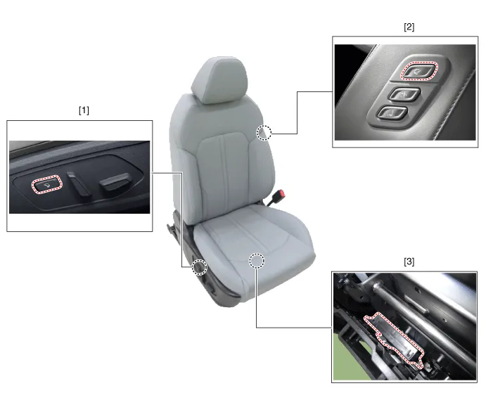
| 1. Relaxion comfort switch
2. Walk-in switch |
3. Relaxion comfort seat unit
(RCSU) |
Schematic diagrams
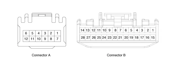
| Connector and Terminal Function |
|
Pin |
Function |
|
|
Connector A |
Connector B |
|
|
1 |
Battery (+) |
Slide motor switch (Forward) |
|
2 |
Slide motor (Forward) |
Slide motor switch (Backward) |
|
3 |
Slide motor (Backward) |
Relaxion comfort switch (Forward) |
|
4 |
Recline motor (Forward) |
Relaxion comfort switch (Backward) |
|
5 |
Recline motor (Backward) |
Rear height motor switch (Up) |
|
6 |
Ground |
Rear height motor switch (Down) |
|
7 |
Battery (+) |
Relaxion comfort switch |
|
8 |
- |
Return switch |
|
9 |
Rear height motor (Up) |
- |
|
10 |
Rear height motor (Down) |
- |
|
11 |
- |
Sensor power |
|
12 |
Ground |
IGN2 |
|
13 |
|
IGN1 |
|
14 |
ECU (Battery +) |
|
|
15 |
Walk-in switch Slide (Forward) |
|
|
16 |
Walk-in switch Slide (Backward) |
|
|
17 |
Walk-in switch Recline (Forward) |
|
|
18 |
Walk-in switch Recline (Backward) |
|
|
19 |
Walk-in relaxion comfort switch |
|
|
20 |
Walk-in return switch |
|
|
21 |
ECU (Ground) |
|
|
22 |
- |
|
|
23 |
- |
|
|
24 |
Limit set power |
|
|
25 |
Slide motor sensor |
|
|
26 |
Recline motor sensor |
|
|
27 |
Rear height motor sensor |
|
|
28 |
Virtual limit set switch |
|
Repair procedures
| Removal |
Walk-in Switch
| 1. |
Remove the walk-in switch. (Refer to Seat Electrical - "Walk-in Switch") |
Relaxion Comfort Switch
| 1. |
Remove the relaxion comfort switch. (Refer to Seat Electrical - "Power Seat Control Switch") |
Relaxion Comfort Seat Unit (RCSU)
| 1. |
Disconnect the negative battery terminal. |
| 2. |
Remove the front passenger seat assembly. (Refer to Body - "Front Seat Assembly") |
| 3. |
Loosen the occupant detection sensor mounting screws (A).
|
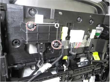
| 4. |
Remove the occupant detection sensor (B) by disconnecting the connector (A).
|
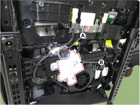
| 5. |
Disconnect the side airbag connector (B) by removing the fixing clip (A).
|
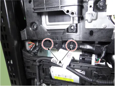
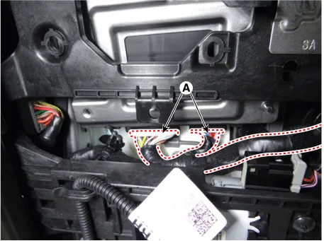
| 6. |
Remove the relaxion comfort seat unit fixing clips (A).
|
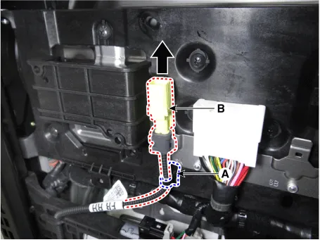
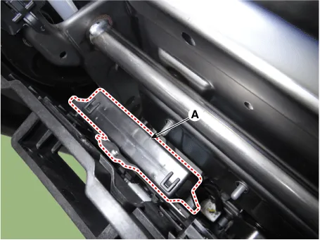
| 7. |
Disconnect the relaxion comfort seat unit connectors (A).
|
| 8. |
Loosen the relaxion comfort seat unit mounting screws (A).
|
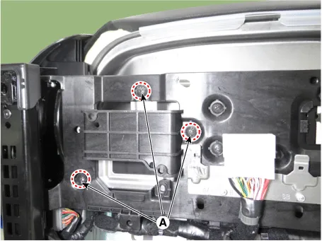
| 9. |
Remove the relaxion comfort seat unit (A).
|
| Installation |
| 1. |
Install in the reverse order of removal. |
Components and components location Component Location 1. Walk-in switch Repair procedures Removal When prying with a flat-tip screwdriver or use a prying trim tool, wrap it with protective tape, and apply protective tape around the related parts, to prevent damage.
Specifications Specifications Smart Key Unit Items Specification Rated voltage DC 12 V Operation voltage DC 9 - 16 V Operation temperature -40 to 185°F (-40 to 85°C) RF Receiver Items Specification Frequency 433.
Other information:
Kia Optima DL3 2019-2026 Service and Repair Manual: Heated Seats Only
Components and components location Components Front Seat Heater 1. Front seat back heater 2. Front seat cushion heater 3. Front seat heater unit / ventilation unit Rear Seat Heater 1.
Kia Optima DL3 2019-2026 Service and Repair Manual: Ventilated and Heated Seat
Schematic diagrams Connector and Terminal Function Pin Function Connector A Connector B 1 Driver heater ground (-) Driver blower speed (+) 2 Passenger heater ground (-) - 3
Categories
- Manuals Home
- Kia Optima Owners Manual
- Kia Optima Service Manual
- Suspension System
- Engine Mechanical System
- Identification Numbers
- New on site
- Most important about car
