Kia Optima DL3: Floor Console / Floor Console Assembly
Components and components location
| Component Location |
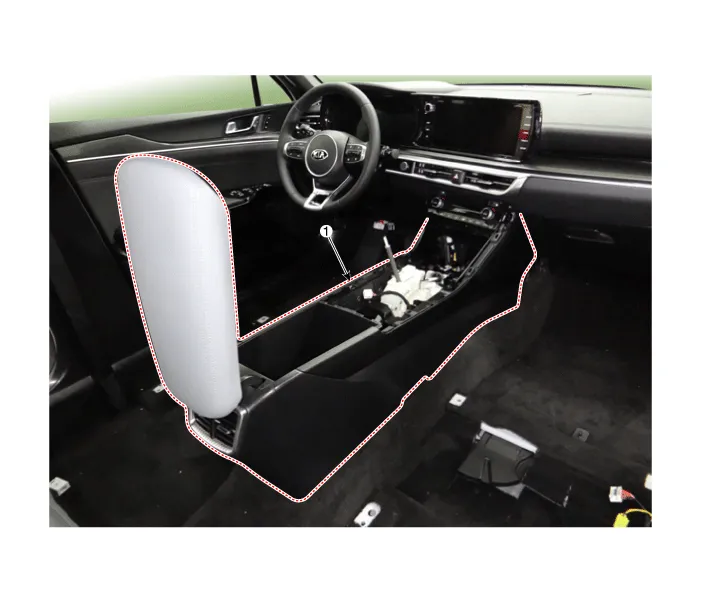
| 1. Front console assembly |
Repair procedures
| Replacement |
[SBC Console]
|

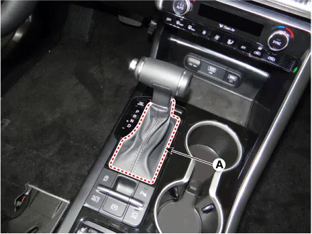
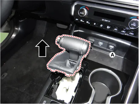
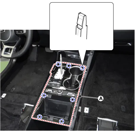
| 1. |
Remove the gear knob & boots (A) by pulling it upwards.
|
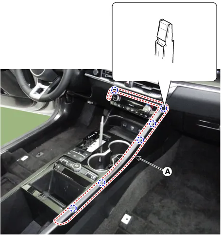
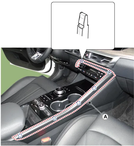
| 2. |
Using a screwdriver or remover, remove the console upper garnish (A).
|
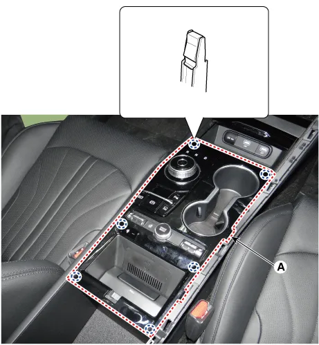
| 3. |
Using a screwdriver or remover, remove the console upper cover (A).
|
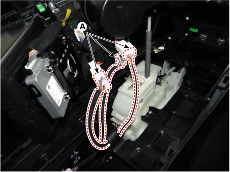
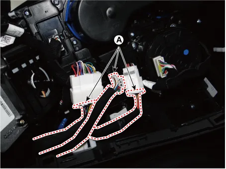
| 4. |
Disconnect the connectors (A).
|
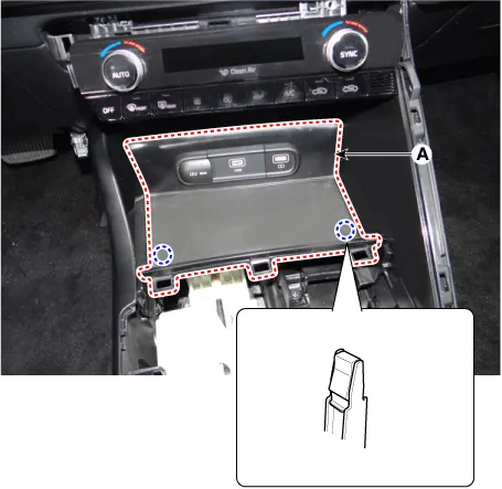
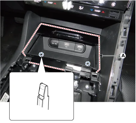
| 5. |
Using a screwdriver or remover, remove the console tray (A).
|
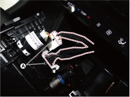
| 6. |
Disconnect the connector (A).
|
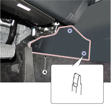
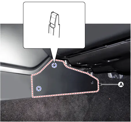
| 7. |
Remove the console side cover (A). [LH]
[RH]
|
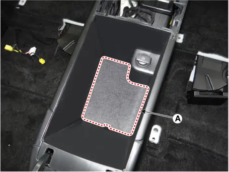
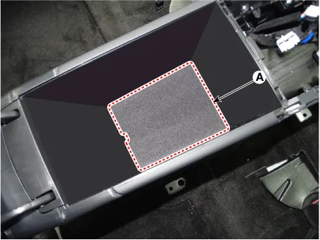
| 8. |
Remove the storage box pad (A).
|
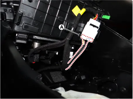
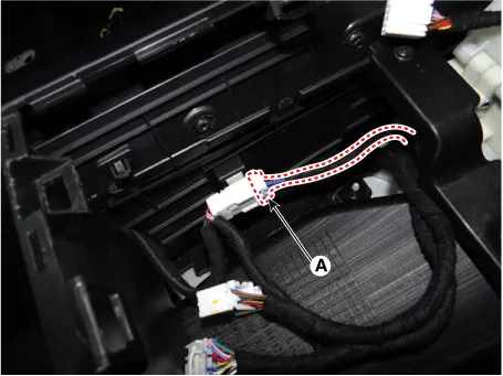
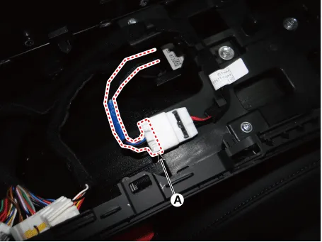
| 9. |
Disconnect the console main connector (A).
|
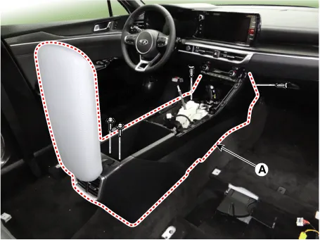
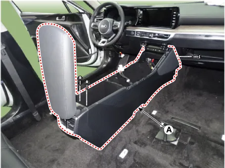
| 10. |
After loosening the mounting screws and bolts, remove the floor console assembly (A).
|
| 11. |
To install, reverse removal procedure.
|

[SBW Console]
|
| 1. |
Using a screwdriver or remover, remove the console upper garnish (A).
|
| 2. |
Using a screwdriver or remover, remove the console upper cover (A).
|
| 3. |
Disconnect the connectors (A).
|
| 4. |
Using a screwdriver or remover, remove the console tray (A).
|
| 5. |
Disconnect the connectors (A).
|
| 6. |
Remove the console side cover (A). [LH]
[RH]
|
| 7. |
Remove the storage box pad (A).
|
| 8. |
Disconnect the console main connector (A).
|
| 9. |
After loosening the mounting screws and bolts, remove the floor console assembly (A).
|
| 10. |
To install, reverse removal procedure.
|
Components and components location Components [SBC Console] 1. Console side cover [LH] 2. Console side cover [RH] 3.
Repair procedures Replacement • When removing with a flat-tip screwdriver or remover, wrap protective tape around the tools to prevent damage to components.
Other information:
Kia Optima DL3 2019-2026 Service and Repair Manual: Power Door Mirror Actuator
Schematic diagrams Connector and Terminal Function Repair procedures Inspection 1. Disconnect the negative battery terminal. 2. Remove the front door trim. (Refer to Body - "Front Door Trim") 3.
Kia Optima DL3 2019-2026 Service and Repair Manual: Air Conditioning System
General safety information and caution Instructions (R-134a) When Handling Refrigerant 1. R-134a liquid refrigerant is highly volatile. A drop on the skin of your hand could result in localized frostbite. When handling the refrigerant, be sure to wear gloves.
Categories
- Manuals Home
- Kia Optima Owners Manual
- Kia Optima Service Manual
- Floor Console Assembly
- Emergency trunk safety release
- Body (Interior and Exterior)
- New on site
- Most important about car
