
Kia Optima DL3: Body (Interior and Exterior) / Floor Console
Components and components location
| Components |
[SBC Console]
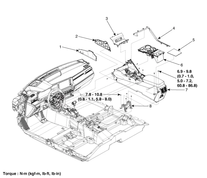
| 1. Console side cover [LH]
2. Console side cover [RH] 3. Console tray 4. Console upper garnish |
5. Console armrest mat 6. Console upper cover 7. Floor console assembly 8. Console rear mounting bracket |
[SBW Console]
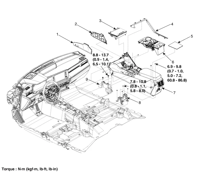
| 1. Console side cover [LH]
2. Console side cover [RH] 3. Console tray 4. Console upper garnish 5. Console armrest mat |
6. Console upper cover 7. Floor console assembly 8. Console rear mounting bracket 9. Console front mounting bracket |
Components and components location Component Location 1. Cowl top cover Repair procedures Replacement • When removing with a flat-tip screwdriver or remover, wrap protective tape around the tools to prevent damage to components.
Components and components location Component Location 1. Front console assembly Repair procedures Replacement [SBC Console] • When removing with a flat-tip screwdriver or remover, wrap protective tape around the tools to prevent damage to components.
Other information:
Kia Optima DL3 2019-2026 Service and Repair Manual: Smart Key System
Specifications Specifications Smart Key Unit Items Specification Rated voltage DC 12 V Operation voltage DC 9 - 16 V Operation temperature -40 to 185°F (-40 to 85°C) RF Receiver Items
Kia Optima DL3 2019-2026 Service and Repair Manual: Condenser
Components and components location Components Location 1. Condenser Repair procedures Inspection 1. Check the condenser fins for clogging and damage. If clogged, clean them with water, and blow them with compressed air.
Categories
- Manuals Home
- Kia Optima Owners Manual
- Kia Optima Service Manual
- Brake System
- Engine Mechanical System
- Cooling System
- New on site
- Most important about car
