Kia Optima DL3: Integrated Memory Seat (IMS) / Integrated Memory Seat (IMS) Unit
Specifications
| Specifications |
|
Item |
Specifications |
|
Rated voltage |
DC 12 V |
|
Operating voltage |
DC 9 - 16 V |
|
Operating temperature range |
-22 to 167°F (-30 to 75°C) |
|
Dark current |
Max. 1.2 mA |
Components and components location
| Component Location |
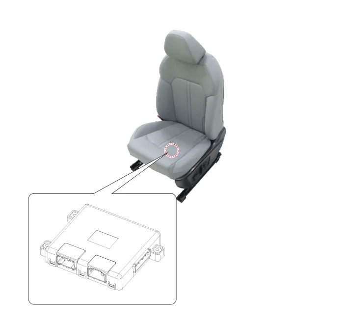
| 1. Integrated memory seat (IMS)
unit |
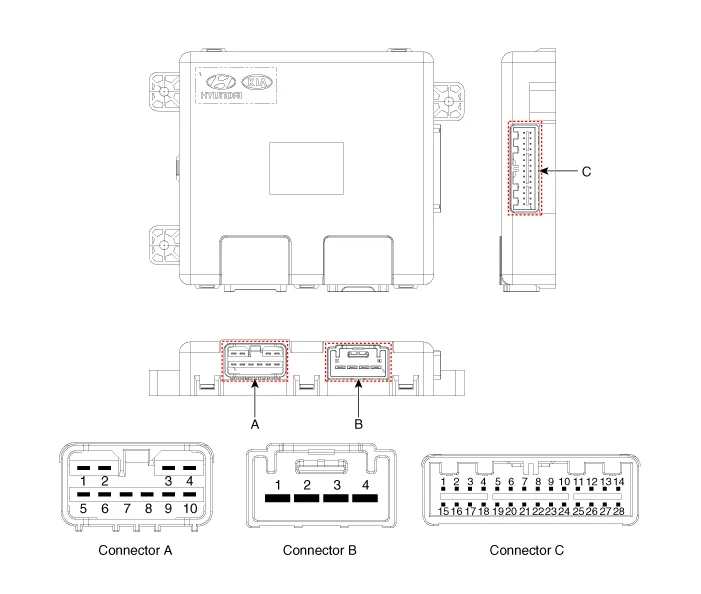
Schematic diagrams
| Connector and Terminal Function |
|
Pin |
Function |
||
|
Connector A |
Connector B |
Connector C |
|
|
1 |
- |
Battery (+) |
Slide switch signal (Forward) |
|
2 |
Recline motor (Forward) |
Battery (+) |
Recline switch signal (Forward) |
|
3 |
Rear height motor (Up) |
Ground |
Front tilt switch signal (Up) |
|
4 |
Slide motor (Forward) |
Ground |
Rear height switch signal (Up) |
|
5 |
- |
|
- |
|
6 |
Recline motor (Backward) |
B-CAN (High) |
|
|
7 |
Front tilt motor (Up) |
B-CAN (Low) |
|
|
8 |
Front tilt motor (Down) |
- |
|
|
9 |
Rear height motor (Down) |
Driver lumbar support motor (Mid) |
|
|
10 |
Slide motor (Backward) |
Slide sensor |
|
|
11 |
|
- |
|
|
12 |
- |
||
|
13 |
Seat position sensor power |
||
|
14 |
IGN1 |
||
|
15 |
Slide switch signal (Backward) |
||
|
16 |
Recline switch signal (Backward) |
||
|
17 |
Front tilt switch signal (Down) |
||
|
18 |
Rear height switch signal (Down) |
||
|
19 |
- |
||
|
20 |
Ground |
||
|
21 |
- |
||
|
22 |
- |
||
|
23 |
Driver lumbar support motor (Def) |
||
|
24 |
- |
||
|
25 |
- |
||
|
26 |
- |
||
|
27 |
- |
||
|
28 |
Battery (+) |
||
Repair procedures
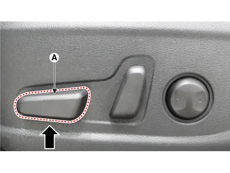
| Removal |
Before removing the driver side seat assembly, pull it upward to the maximum by pushing the front seat height adjusting switch (A).
|

| 1. |
Disconnect the negative battery terminal. |
| 2. |
Remove the front drive seat assembly. (Refer to Body - "Front Seat Assembly") |
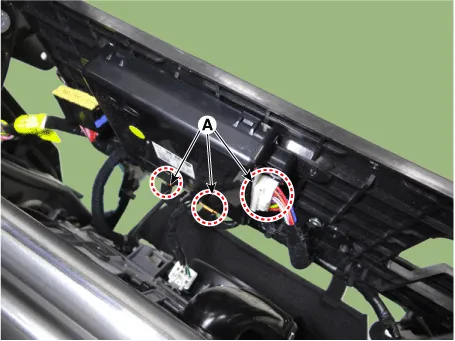
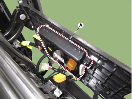
| 3. |
Disconnect the IMS unit connectors (A).
|
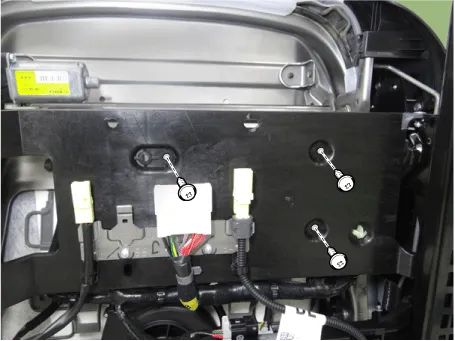
| 4. |
Remove the IMS unit (A) by loosening the mounting screws.
|
| Installation |
| 1. |
Install in the reverse order of removal. |
| Inspection |
| 1. |
In the body electrical system, failure can be quickly diagnosed by using the vehicle diagnostic system (KDS). The diagnostic system (KDS) provides the following information.
|
| 2. |
Select the 'Car model' and the 'Power Seat Module (PSM)' to be checked in order to check the vehicle with the tester. |
| 3. |
Select the 'Current Data' menu to search the current state of the input/output data. The input/output data for the sensors corresponding to the power seat module (PSM) can be checked. |
| 4. |
To forcibly actuate the input value of the module to be checked, select option 'Actuation Test'. |
Schematic diagrams Connector and Terminal Function Repair procedures Removal When prying with a flat-tip screwdriver or use a prying trim tool, wrap it with protective tape, and apply protective tape around the related parts, to prevent damage.
Other information:
Kia Optima DL3 2019-2026 Service and Repair Manual: Smart Key Unit
Schematic diagrams Connector and Terminal Function Pin Function Connector A Connector B Connector C Connector D 1 - Front washer switch (Output) - Driver outside handle switch (Input)
Kia Optima DL3 2019-2026 Service and Repair Manual: Blower Unit
Components and components location Component Location 1. Blower unit assembly Components 1. Intake actuator 2. Cluster ionizer 3. Air filter 4. Blower motor assembly 5.
Categories
- Manuals Home
- Kia Optima Owners Manual
- Kia Optima Service Manual
- Floor Console Assembly
- Charging System
- Lift And Support Points
- New on site
- Most important about car
