Kia Optima DL3: Head Up Display System / Head Up Display (HUD) Unit
Schematic diagrams
| Connector and Terminal Function |
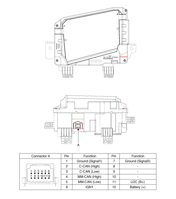
Repair procedures
| • |
Use a plastic panel removal tool to remove interior trim pieces
without marring the surface.
|
| • |
Take care not to bend or scratch the trim and panels.
|
|
| 1. |
Remove the cluster assembly.
(Refer to Indicators And Gauges - "Instrument Cluster")
|
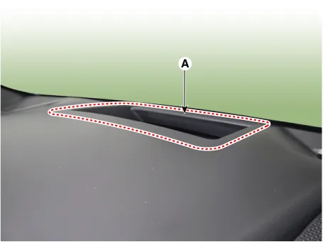
| 2. |
Remove the head up display upper cover (A) by using a screwdriver or
remover.
|
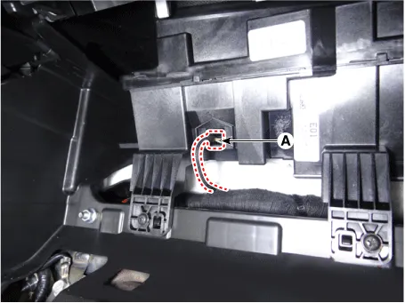
| 3. |
Disconnect the head up display unit connector (A).
|
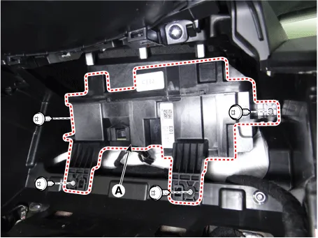
| 4. |
Remove the head up display unit (A) by loosening the mounting screws.
|
| 1. |
Install in the reverse order of removal.
|
If a part of the head up display image is distorted or it is not at eye level
with the driver, the diagnostic system (KDS) can be used to carry out calibration.
| 1. |
Calibration is required:
| – |
After replacing the head-up display unit
|
| – |
When the image is distorted after replacing the windshield (double
vision removal film built-in glass)
|
| – |
When the HUD mounted main crash pad is removed/installed or replaced.
|
| – |
When the image setting location of the HUD unit is not at eye
level of the driver resulting in out of focus image.
|
|
| 2. |
Calibration items
No
|
Image calibration functions
|
Calibration cases
|
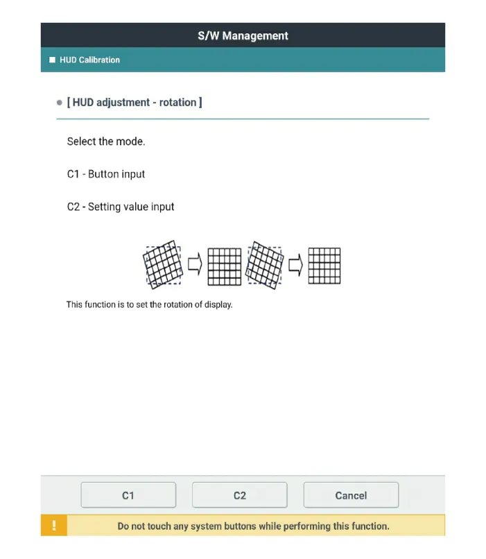
1
|
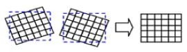
Can calibrate clockwise/counter clockwise to center image
|
|
2
|
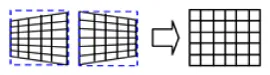
Smile: Calibrate vertically to center.
|

|
3
|
Slanted (up/down): Calibrate along a vertical inclination.
|

|
4
|
Slanted (left/right): Calibrate along a horizontal inclination.
|
|
5
|
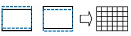
Parallel compensation
|

|
6
|
Up/down movement of indicated location: Calibrate to driver's level.
|
|
7
|
Initialization: Return to previous status before calibration.
|
|
|
| 3. |
Calibration procedure
| (1) |
Park the vehicle on a flat plane for accurate adjustment.
|
| (2) |
Make sure that there are no foreign materials on the windshield.
|
| (3) |
Connect the KDS to the vehicle, and select vehicle type and HUD
system additional functions.
|
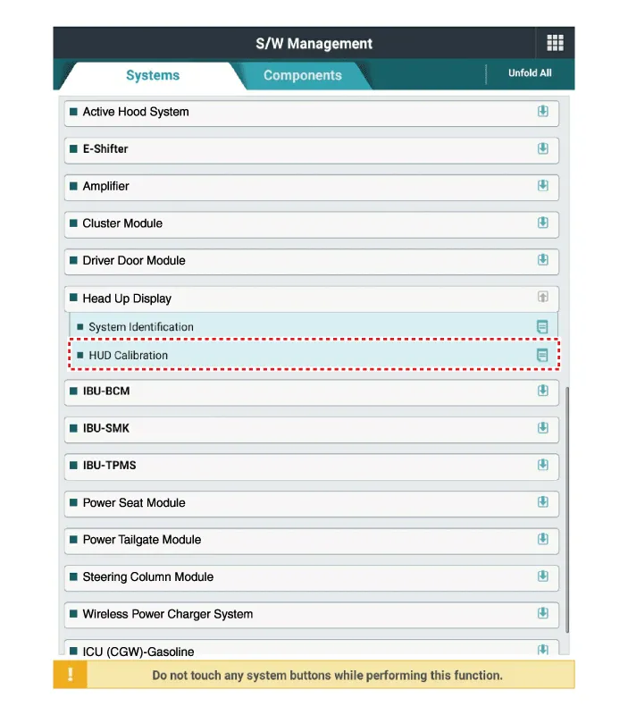
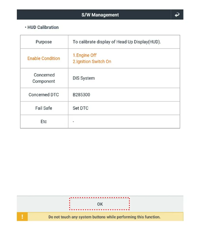
| (4) |
Under additional functions select 'HUD calibration'.
|
| (5) |
Before 'calibration', perform 'HUD calibration - initialization'.
|
'HUD calibration - initialization' must be performed
prior to 'calibration'.
|
|
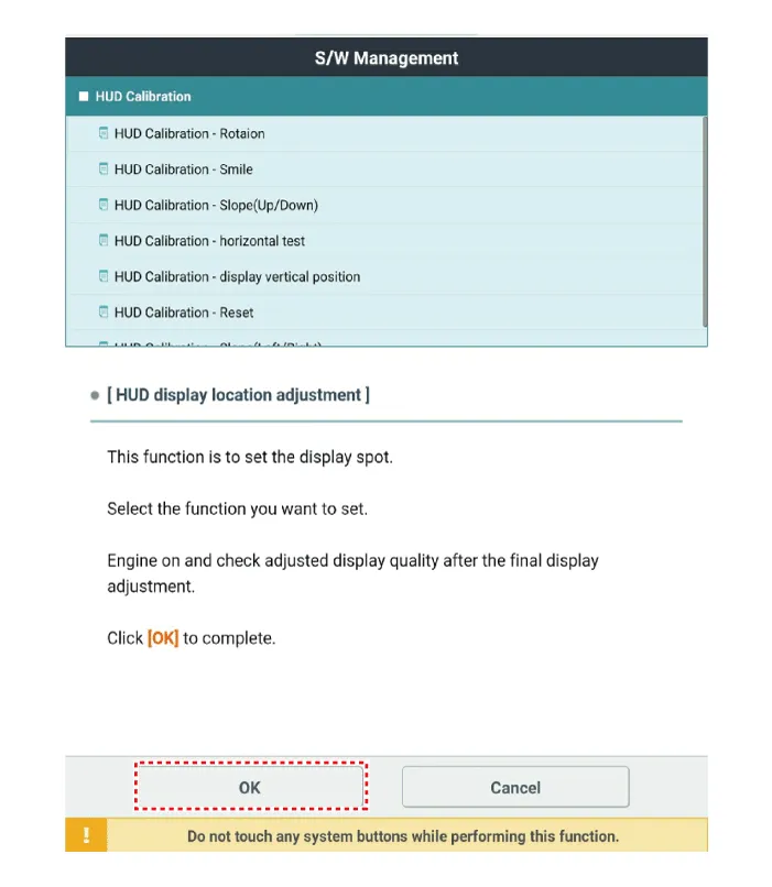
| (6) |
Select the necessary calibration items and perform 'HUD calibration'.
|
| (7) |
When calibration is completed, start and cut off the engine and
check that the image calibration is completed.
|
|
Components and components location
Components Location
1. Rain sensor
2. Head up display (HUD) unit
3. Instrument cluster
Description and operation
Description
HUD system displays various information on the windshield glass which minimizes
the driver’s eye movement to enhance safety and convenience.
Specifications
Specifications
Item
Specification
Remark
Operating voltage
9 - 16 V
-
Current consumption
MAX 5.
Other information:
Repair procedures
Removal
1.
Disconnect the negative battery terminal.
2.
Remove the roof trim assembly.
(Refer to Body - "Roof Trim Assembly")
3.
Disconnect the high mounted stop lamp connector (A).
Repair procedures
Inspection
Power Window Main Switch
Diagnosis With KDS
1.
In the body electrical system, failure can be quickly diagnosed by using
the vehicle diagnostic system (KDS).
The diagnostic system (KDS) provides the following information.

