Tool Name / Number
|
Illustration
|
Description
|
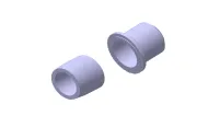
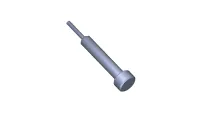
Crankshaft front oil seal installer
09231-2E000
|
|
Used for installing crankshaft front oil seal
|
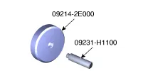
Crankshaft rear oil seal installer
09214-2E000 (Installer)
09231-H1100 (Handle)
|
|
Used for installing crankshaft rear oil seal
|
Valve spring compressor & holder
09222-3K000 (Compressor)
09222-3K100 (Handle)
|

|
Used for removing / installing intake or exhaust valve
|
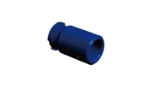
Valve stem seal installer
09222-2E000
|
|
Used for installing valve stem seal
|
Ring gear stopper
09231-3N100
09231-2B100
|

|
Used for keeping ring gear from rotating when removing / installing crankshaft
pulley bolt
|
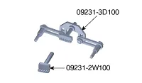
Ring gear stopper
09231-3D100
09231-2W100
|
|
Used for keeping ring gear from rotating when removing / installing crankshaft
pulley bolt
|
Oil pan remover
09215-3C000
|

|
Used for removing oil pan
|
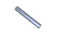
Tensioner stopper pin
09240-2E100
|
|
Used for holding compressed piston of tensioner
|
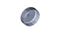
Oil filter wrench
09263-2E000
|
|
Used for removing / installing oil filter
|
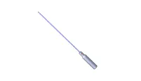
Steel ball installer
0K221-2M100
|
|
Used for installing steel ball
|
Pressure cap pressure checker
0K253-G5100
|
|
Used for checking for pressure cap pressure and a coolant leak
|
Symptom
|
Suspect area
|
Remedy
|
Engine misfire with abnormal internal lower engine noises
|
| • |
Worn crankshaft bearings
|
| • |
Loose or out of specification engine flywheel
|
|
| • |
Replace the crankshaft and bearings as required.
|
| • |
Repair or replace the flywheel as required.
|
|
Worn piston rings
(Oil consumption may or may not cause the engine to misfire.)
|
Inspect the cylinder for a loss of compression.
Repair or replace as required.
|
Worn crankshaft thrust bearings
|
Replace the crankshaft and bearings as required
|
Engine misfire with abnormal valve train noise
|
Stuck valves
(Carbon buildup on the valve stem)
|
Repair or replace as required.
|
Excessive worn or mis-aligned timing chain
|
Replace the timing chain and sprocket as required.
|
Worn camshaft lobes
|
Replace the camshaft.
|
Engine misfire with coolant consumption
|
| • |
Faulty cylinder head gasket or other damage to the cylinder head
and engine block cooling system
|
| • |
Coolant consumption may or may not cause the engine to overheat
|
|
| • |
Inspect the cylinder head and engine block for damage to the
coolant passages and/or a faulty head gasket.
|
| • |
Repair or replace as required.
|
|
Engine misfire with excessive oil consumption
|
Worn valves, guides and/or valve stem oil seals
|
Repair or replace as required.
|
Worn piston rings
(Oil consumption may or may not cause the engine to misfire)
|
| • |
Inspect the cylinder for a loss of compression.
|
| • |
Repair or replace as required.
|
|
Engine noise on start-up, but only lasting a few seconds
(Check and compare with known good vehicle to determine normal condition.)
|
Incorrect oil viscosity
|
| • |
Install the correct viscosity oil.
|
|
Worn crankshaft thrust bearing
|
| • |
Inspect the thrust bearing and crankshaft.
|
| • |
Repair or replace as required.
|
|
Upper engine noise, regardless of engine speed
|
Low oil pressure
|
Repair or replace as required.
|
Broken valve spring
|
Replace the valve spring.
|
Worn or dirty valve lifters
|
Replace the valve lifters.
|
Stretched or broken timing chain and/or damaged sprocket teeth
|
Replace the timing chain and sprockets.
|
Worn timing chain tensioner, if applicable
|
Replace the timing chain tensioner as required.
|
Worn camshaft lobes
|
| • |
Inspect the camshaft lobes.
|
| • |
Replace the camshaft as required.
|
|
Worn valve guides or valve stems
|
Inspect the valves and valve guides, then repair or replace as required.
|
Stuck valves (Carbon on the valve stem or valve seat may cause the valve
to stay open.)
|
Inspect the valves and valve guides, then repair or replace as required.
|
Worn drive belt, idler, tensioner and bearing
|
Replace as required.
|
Lower engine noise, regardless of engine speed
|
Low oil pressure
|
Repair or required.
|
Loose or damaged flywheel
|
Repair or replace the flywheel.
|
Damaged oil pan, contacting the oil pump screen
|
| • |
Inspect the oil pump screen.
|
| • |
Repair or replace as required.
|
|
Oil pump screen loose, damaged or restricted
|
| • |
Inspect the oil pump screen.
|
| • |
Repair or replace as required.
|
|
Excessive piston-to-cylinder bore clearance
|
| • |
Inspect the piston, piston pin and cylinder bore.
|
| • |
Repair or replace as required.
|
|
Excessive piston pin-to-piston clearance
|
| • |
Inspect the piston, piston pin and the connecting rod.
|
| • |
Repair or replace as required.
|
|
Excessive connecting rod bearing clearance
|
Inspect the following components and repair or replace as required.
| • |
The connecting rod bearings.
|
| • |
The crankshaft pin journals.
|
|
Excessive crankshaft bearing clearance
|
Inspect the following components, and repair or replace as required.
| • |
The crankshaft bearings.
|
| • |
The crankshaft main journals.
|
|
Incorrect piston, piston pin and connecting rod installation
|
| • |
Verify the piston pins and connecting rods are installed correctly.
|
|
Engine noise under load
|
Low oil pressure
|
Repair or replace as required.
|
Excessive connecting rod bearing clearance
|
Inspect the following components and repair or replace as required:
| • |
The connecting rod bearings
|
|
Excessive crankshaft bearing clearance
|
Inspect the following components, and repair or replace as required:
| • |
The crankshaft bearings
|
| • |
The crankshaft main journals
|
|
Engine is not cranked.
Crankshaft does not rotate.
|
Hydraulically locked cylinder
| • |
Coolant/antifreeze in cylinder
|
|
| 1) |
Remove spark plugs and check for fluid.
|
| 2) |
Inspect for broken head gasket.
|
| 3) |
Inspect for cracked engine block or cylinder head.
|
| 4) |
Inspect for a sticking fuel injector and/or leaking fuel regulator.
|
|
Broken timing chain and/or timing chain gears
|
| 1) |
Inspect timing chain and gears.
|
|
Material in cylinder
|
| 1) |
Inspect cylinder for damaged components and/or foreign materials.
|
| 2) |
Repair or replace as required.
|
|
Seized crankshaft or connecting rod bearings
|
| 1) |
Inspect crankshaft and connecting rod bearing.
|
|
Bent or broken connecting rod
|
| 1) |
Inspect connecting rods.
|
|
Broken crankshaft
|
|
Description
|
Specifications
|
Limit
|
General
|
Type
|
In - line, DOHC
|
|
Number of cylinders
|
4
|
|
Bore
|
81.0 mm (3.1890 in.)
|
|
Stroke
|
97.0 mm (3.8189 in.)
|
|
Total displacement
|
1999 cc (121.99 cu.in.)
|
|
Compression ratio
|
10.3±0.2 : 1
|
|
Firing order
|
1 - 3 - 4 - 2
|
|
Valve timing
|
Intake valve
|
Open
|
ATDC 10° - BTDC 40°
|
|
Close
|
ABDC 67° - ABDC 17°
|
|
Exhaust valve
|
Open
|
BBDC 54° - BBDC 14°
|
|
Close
|
ATDC 1° - ATDC 41°
|
|
Camshaft
|
Cam height
|
Intake
|
39.0 mm (1.5354 in.)
|
|
Exhaust
|
38.66 mm (1.5220 in.)
|
|
Journal outer diameter
|
Intake
|
No.1 : 35.959 - 35.975 mm
(1.41571 - 1.41634 in.)
No.2,3,4,5 : 22.959 - 22.975 mm
(0.90390 - 0.90453 in.)
|
|
Exhaust
|
No.1 : 35.959 - 35.975 mm
(1.41571 - 1.41634 in.)
No.2,3,4,5 : 22.959 - 22.975 mm
(0.90390 - 0.90453 in.)
|
|
Bearing oil clearance
|
Intake
|
No.1 : 0.032 - 0.062 mm
(0.00126 - 0.00244 in.)
No.2,3,4,5 : 0.032 - 0.062 mm
(0.00126 - 0.00244 in.)
|
|
Exhaust
|
No.1 : 0.032 - 0.062 mm
(0.00126 - 0.00244 in.)
No.2,3,4,5 : 0.032 - 0.062 mm
(0.00126 - 0.00244 in.)
|
|
End play
|
0. 10 - 0.19 mm (0.0039 - 0.0075 in.)
|
|
Valve
|
Valve length
|
Intake
|
102.22 mm (4.0244 in.)
|
101.97 mm (4.0146 in.)
|
Exhaust
|
104.04 mm (4.0961 in.)
|
103.79 mm (4.0862 in.)
|
Stem outer diameter
|
Intake
|
5.465 - 5.480 mm (0.21516 - 0.21575 in.)
|
|
Exhaust
|
5.458 - 5.470 mm (0.21488 - 0.21535 in.)
|
|
Face angle
|
45.25° - 45.75°
|
|
Thickness of valve head(margin)
|
Intake
|
1.30 mm (0.0512 in.)
|
|
Exhaust
|
1.26 mm (0.0496 in.)
|
|
Valve stem to valve guide clearance
|
Intake
|
0.020 - 0.047 mm (0.00079 - 0.00185 in.)
|
|
Exhaust
|
0.030 - 0.054 mm (0.00118 - 0.00213 in.)
|
|
Valve guide
|
Length
|
Intake
|
43.8 - 44.2 mm (1.7244 - 1.7402 in.)
|
|
Exhaust
|
43.8 - 44.2 mm (1.7244 - 1.7402 in.)
|
|
Inner diameters
|
Intake
|
5.500 - 5.512 mm (0.21654 - 0.21701 in.)
|
|
Exhaust
|
5.500 - 5.512 mm (0.21654 - 0.21701 in.)
|
|
Valve seat
|
Width of seat contact
|
Intake
|
1.05 - 1.35 mm (0.0413 - 0.0532 in.)
|
|
Exhaust
|
1.35 - 1.65 mm (0.0532 - 0.0650 in.)
|
|
Seat angle
|
Intake
|
44° 45' - 45° 6'
|
|
Exhaust
|
44° 45' - 45° 6'
|
|
Valve spring
|
Free length
|
45.93 mm (1.8083 in.)
|
|
Load
|
19.6 ± 1.0 kg / 37.0 mm
(43.21 ± 2.20 lb / 1.4567 in.)
45.7 ± 1.8 kg / 27.0 mm
(100.75 ± 3.97 lb / 1.0630 in.)
|
|
Out of squareness
|
Less than 1.5°
|
|
Cylinder head
|
Flatness of gasket surface
|
Less than 0.05 mm (0.0020 in.) for total area
Less than 0.02 mm (0.0008 in.) for a section of
100 mm (3.9370 in.) × 100 mm (3.9370 in.)
|
|
Flatness of manifold mounting surface
|
Intake
|
Less than 0.10 mm (0.0039 in.)
|
|
Exhaust
|
Less than 0.10 mm (0.0039 in.)
|
|
Piston
|
Piston outer diameter
|
80.97 - 81.00 mm (3.1878 - 3.1890 in.)
|
|
Piston to cylinder clearance
|
0.02 - 0.04 mm (0.0008 - 0.0016 in.)
|
|
Ring groove width
|
No. 1 ring
|
1.030 - 1.050 mm (0.04055 - 0.04134 in.)
|
|
No. 2 ring
|
1.230 - 1.250 mm (0.04843 - 0.04921 in.)
|
|
Oil ring
|
2.010 - 2.025 mm (0.07913 - 0.07972 in.)
|
|
Piston ring
|
Side clearance
|
No. 1 ring
|
0.040 - 0.080 mm (0.00157 - 0.00315 in.)
|
|
No. 2 ring
|
0.040 - 0.080 mm (0.00157 - 0.00315 in.)
|
|
Oil ring
|
0.040 - 0.115 mm (0.00157 - 0.00453 in.)
|
|
End gap
|
No. 1 ring
|
0.15 - 0.30 mm (0.0059 - 0.0118 in.)
|
|
No. 2 ring
|
0.30 - 0.45 mm (0.0118 - 0.0177 in.)
|
|
Oil ring
|
0.20 - 0.70 mm (0.0079 - 0.0276 in.)
|
|
Piston pin
|
Piston pin outer diameter
|
19.997 - 20.000 mm (0.78728 - 0.78740 in.)
|
|
Piston pin hole inner diameter
|
20.004 - 20.009 mm (0.78756 - 0.78775 in.)
|
|
Piston pin hole clearance
|
0.004 - 0.012 mm (0.00016 - 0.00047 in.)
|
|
Connecting rod small end hole inner diameter
|
20.007 - 20.015 mm (0.78768 - 0.78799 in.)
|
|
Piston pin - to - connecting rod bushing oil clearance
|
0.007 - 0.018 mm (0.00028 - 0.00070 in.)
|
|
Connecting rod
|
Connecting rod big end inner diameter
|
48.000 - 48.018 mm (1.88976 - 1.89047 in.)
|
|
Connecting rod bearing oil clearance
|
0.024 - 0.042 mm (0.00094 - 0.00165 in.)
|
|
Side clearance
|
0.10 - 0.25 mm (0.0039 - 0.0098 in.)
|
|
Crankshaft
|
Main journal outer diameter
|
54.942 - 54.960 mm (2.16307 - 2.16378 in.)
|
|
Pin journal outer diameter
|
44.954 - 44.972 mm (1.76984 - 1.77055 in.)
|
|
Main bearing oil clearance
|
0.016 - 0.034 mm (0.00063 - 0.00134 in.)
|
|
End play
|
0.07 - 0.25 mm (0.0028 - 0.0098 in.)
|
|
Cylinder block
|
Cylinder bore
|
81.00 - 81.03 mm (3.1890 - 3.1902 in.)
|
|
Flatness of gasket surface
|
Less than 0.05 mm (0.0020 in.) for total area
Less than 0.02 mm (0.0008 in.) for a section of 100 mm (3.9370 in.) × 100
mm (3.9370 in.)
|
|
Cooling system
|
Cooling method
|
Forced circulation with cooling fan
|
|
Coolant quantity
|
Approx. 6.3 L (1.66 U.S.gal., 6.66 U.S.qt., 5.54 lmp.qt.)
|
|
Thermostat
|
Type
|
Wax pellet type
|
|
Opening
temperature
|
88±1.5°C (190.4±34.7°F)
|
|
Full opening valve lift / temperature
|
More than 8 mm (0.3 in.) / 100°C (212°F)
|
|
Radiator cap
|
Main valve opening pressure
|
125.52 - 154.94 kpa
(1.28 - 1.58 kg/cm², 18.21 - 22.47 psi).
|
|
Vacuum valve opening pressure
|
0 - 6.86 kPa (0 - 0.07 kgf/cm², 0 - 1.00 psi)
|
|
Description
|
Specifications
|
Limit
|
Engine oil
|
Oil quantity
|
Total
|
4.5 L (1.19 U.S.gal., 4.76 U.S.qt., 3.96 lmp.qt.)
|
When replacing a short engine or block assembly
|
Oil pan
|
3.7 L (0.98 U.S.gal., 3.91 U.S.qt., 3.26 lmp.qt.)
|
|
Drain and refill
|
4.0 L (1.06 U.S.gal., 4.23 U.S.qt., 3.52 lmp.qt.)
|
Including oil filter
|
Oil grade
|
Specifications
|
All (Except Middle east, India, Libia, Algeria, Morocco, Tunisia, Sudan,
Egypt, Iran) :
- ILSAC GF-4 & API SM or above / 5W-20
- ACEA A5 or above / 5W-20
Middle east, India, Libia, Algeria, Morocco, Tunisia, Sudan, Egypt, Iran
:
- ACEA A5 or above / 5W-30
|
If oil of acceptable viscosity is not available, refer to "Lubrication
System" for recommended SAE viscosity number
|
|
|
Oil pressure (at 1,000rpm)
|
98.07 kPa (1.0 kgf/cm², 14.22 psi) or above
|
Oil temperature (oil pan): 110±2°C (230±35.6°F)
|
Item
|
N•m
|
kgf•m
|
lb•ft
|
lb•inIb.in
|
Engine mounting
|
Engine mounting bracket and body fixing blots
|
68.6 - 88.3
|
7.0 - 9.0
|
50.6 - 65.1
|
|
Engine mounting support bracket and engine support bracket fixing bolt
|
88.3 - 107.9
|
9.0 - 11.0
|
65.1 - 79.6
|
|
Engine mounting support bracket and engine support bracket fixing nuts
|
88.3 - 107.9
|
9.0 - 11.0
|
65.1 - 79.6
|
|
Engine mounting insulator and engine support bracket fixing nut
|
88.3 - 107.9
|
9.0 - 11.0
|
65.1 - 79.6
|
|
Transaxle mounting bracket and body fixing bolts
|
68.6 - 88.3
|
7.0 - 9.0
|
50.6 - 65.1
|
|
Transaxle mounting insulator and transaxle support bracket fixing bolts
|
107.9 - 127.5
|
11.0 - 13.0
|
79.6 - 94.0
|
|
Roll rod bracket and sub frame fixing bolts
|
49.0 - 63.7
|
5.0 - 6.5
|
36.1 - 47.0
|
|
Roll rod bracket to roll rod support bracket fixing bolt
|
107.9 - 127.5
|
11.0 - 13.0
|
79.6 - 94.0
|
|
Cylinder head
|
Engine cover mounting bolt
|
7.8 - 9.8
|
0.8 - 1.0
|
5.8 - 7.2
|
|
Cylinder head cover bolt
|
[3.9 - 5.9] + [7.8 - 9.8]
|
[0.4 - 0.6] + [0.8 - 1.0]
|
[2.9 - 4.3] + [5.8 - 7.2]
|
[34.5 - 52.1] + [69.0 - 86.7]
|
CVVT bolt (LH/RH)
|
64.7 - 76.5
|
6.6 - 7.8
|
47.7 - 56.4
|
|
Camshaft bearing cap bolt (M6)
|
11.8 - 13.7
|
1.2 - 1.4
|
8.7 - 10.1
|
|
Camshaft bearing cap bolt (M8)
|
18.6 - 22.6
|
1.9 - 2.3
|
13.7 - 16.6
|
|
Cam carrier bolt
|
18.6 - 22.6
|
1.9 - 2.3
|
13.7 - 16.6
|
|
Cylinder head bolt
|
[32.4 - 36.3] + [90 - 95°] + [90 - 95°]
|
[3.3 - 3.7] + [90 - 95°] + [90 - 95°]
|
[23.9 - 26.8] + [90 - 95°] + [90 - 95°]
|
|
Engine hanger bolt (Front/Rear)
|
34.3 - 39.2
|
3.5 - 4.0
|
25.3 - 28.9
|
|
Camshaft position sensor (LH/RH)
|
9.8 - 11.8
|
1.0 - 1.2
|
7.2 - 8.7
|
|
Oil control valve (OCV) bolt (LH/RH)
|
9.8 - 11.8
|
1.0 - 1.2
|
7.2 - 8.7
|
|
Cylinder block
|
Drive plate bolt (A/T)
|
117.7 - 127.5
|
12.0 - 13.0
|
86.8 - 93.9
|
|
Connecting rod bearing cap bolt
|
[17.7 - 21.6] + [88 - 92°]
|
[1.8 - 2.2] + [88 - 92°]
|
[13.0 - 15.9] + [88 - 92°]
|
|
Lower crankcase bolt
|
18.6 - 23.5
|
1.9 - 2.4
|
13.7 - 17.4
|
|
Main bearing cap bolt
|
[27.5 - 31.4] + [120 - 125°]
|
[2.8 - 3.2] + [120 - 125°]
|
[20.3 - 23.1] + [120 - 125°]
|
|
Crankshaft position sensor bolt
|
10.8 - 11.8
|
1.1 - 1.2
|
8.0 - 8.7
|
|
Knock sensor
|
18.6 - 23.5
|
1.9 - 2.4
|
13.7 - 17.4
|
|
Lubrication system
|
Oil drain plug
|
34.3 - 44.1
|
3.5 - 4.5
|
25.3 - 32.5
|
|
Oil filter
|
11.8 - 15.7
|
1.2 - 1.6
|
8.7 - 11.6
|
|
Oil pan bolt
|
11.8 - 13.7
|
1.2 - 1.4
|
8.7 - 10.1
|
|
Oil screen bolt
|
19.6 - 26.5
|
2.0 - 2.7
|
14.5 - 19.5
|
|
Oil screen nut
|
11.8 - 13.7
|
1.2 - 1.4
|
8.7 - 10.1
|
|
Oil pressure switch
|
9.8 - 11.8
|
1.0 - 1.2
|
7.2 - 8.7
|
|
Cooling system
|
Water pump pulley bolt
|
9.8 - 11.8
|
1.0 - 1.2
|
7.2 - 8.7
|
|
Water pump bolt
|
9.8 - 11.8
|
1.0 - 1.2
|
7.2 - 8.7
|
|
Water inlet fitting nut
|
18.6 - 23.5
|
1.9 - 2.4
|
13.7 - 17.4
|
|
Water temperature control assembly bolt
|
9.8 - 11.8
|
1.0 - 1.2
|
7.2 - 8.7
|
|
Heater pipe bolt
|
19.6 - 23.5
|
2.0 - 2.4
|
14.5 - 17.4
|
|
Intake and exhaust system
|
Air cleaner assembly bolt
|
7.8 - 9.8
|
0.8 - 1.0
|
5.8 - 7.2
|
|
Electronic throttle control (ETC) module bolt
|
9.8 - 11.8
|
1.0 - 1.2
|
7.2 - 8.7
|
|
Intake manifold stay bolt
|
18.6 - 23.5
|
1.9 - 2.4
|
13.7 - 17.4
|
|
Intake manifold bolt
|
18.6 - 23.5
|
1.9 - 2.4
|
13.7 - 17.4
|
|
Intake manifold nut
|
18.6 - 23.5
|
1.9 - 2.4
|
13.7 - 17.4
|
|
Exhaust manifold heat protector bolt
|
9.8 - 11.8
|
1.0 - 1.2
|
7.2 - 8.7
|
|
Exhaust manifold stay bolt
|
39.2 - 49.0
|
4.0 - 5.0
|
28.9 - 36.2
|
|
Exhaust manifold nut
|
29.4 - 34.3
|
3.0 - 3.5
|
21.7 - 25.3
|
|
Muffler nut
|
39.2 - 58.8
|
4.0 - 6.0
|
28.9 - 43.4
|
|