Kia Optima DL3: Automatic Transaxle Control System / Inhibitor Switch
Specifications
| Specification |
|
Item |
Specification |
|
|
Power supply (V) |
4.5 - 5.5 V |
|
|
Output type |
Shifting range (P/R/N/D) |
Non-contact(2 channel PWM signal) |
|
Start, Back-up lamp |
Contact |
|
Description and operation
| Description |
| • |
The inhibitor switch mounted on the upper of transaxle and connected with shifter lever. |
| • |
The inhibitor switch signals delivered at the TCM according to control of the shift lever positions (P, R, N, D) and it is used to control of the gear setting. |
| • |
When the shift lever is placed in R range, send the output signal to the back-up lamps. |
| • |
When the shift lever is placed in P or N range, send the output signal to the start relay.
|
Troubleshooting
| Troubleshooting |
Components and components location
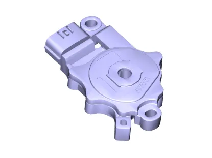
| Component |
| 1. Manual Control Lever |
2. Inhibitor Switch |
Repair procedures
| Inspection |
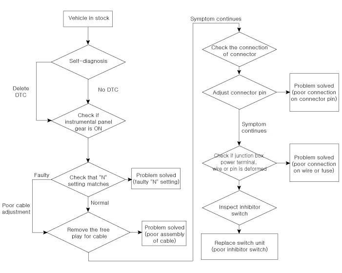
Inspect the following items by referring to inspection flow chart. (Refer to Inhibitor Switch - "Troubleshooting") |

| 1. |
Check the diagnostic trouble codes (DTC) using KDS. |
| 2. |
Check that "N" range setting matches. (Refer to Inhibitor Switch - "Installation") |
| 3. |
Check the free play for shift cable. (Refer to Shift Cable - "Installation") |
| 4. |
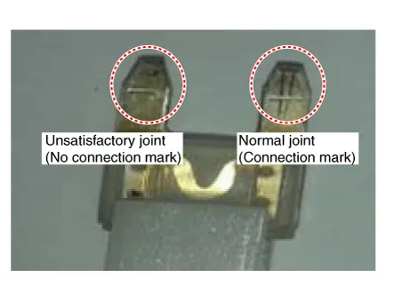
Check the condition of connector.
|
| 5. |
Inspect the wiring connection of junction box power terminal and fuse lamp.
|

| 6. |
Check the inhibitor switch circuit signal.
|
| Removal |
| 1. |
Shift the gear to "N". |
| 2. |
Remove the air cleaner assembly. (Refer to Engine Mechanical System - "Air cleaner") |
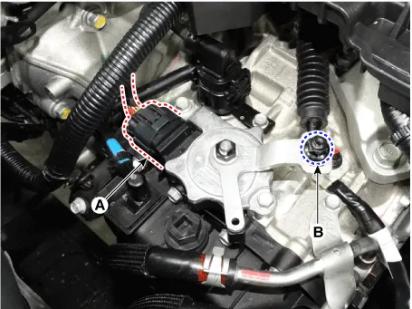
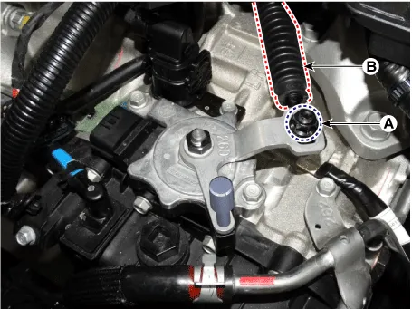
| 3. |
Disconnect the inhibitor switch connector (A) and loosen the shift cable mounting nut (B).
|
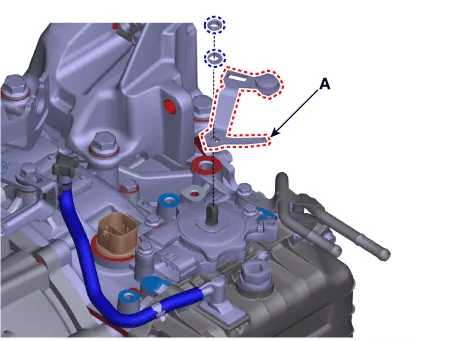
| 4. |
Remove the manual control lever (A) after loosening the nut and washer.
|
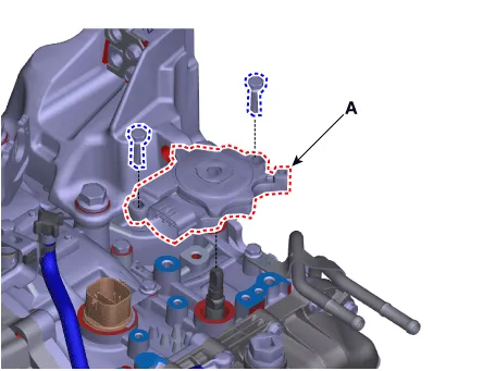
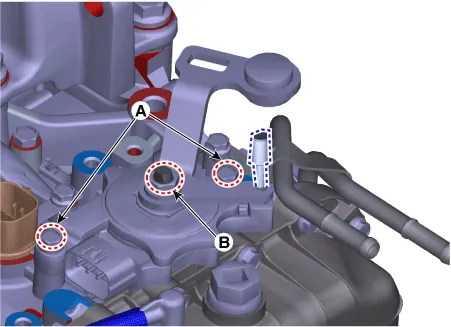
| 5. |
Remove the inhibitor switch (A) after removing the bolts.
|
| Installation |
| 1. |
Check that the gear is shifted to "N". |
| 2. |
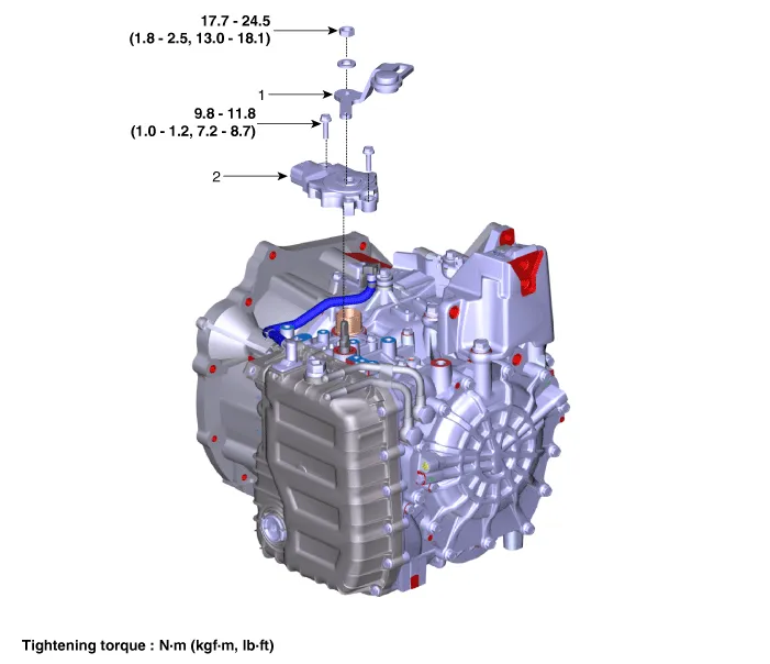
Install the inhibitor switch (A).
|

| 3. |
Install the manual control lever (A) and washer.
|
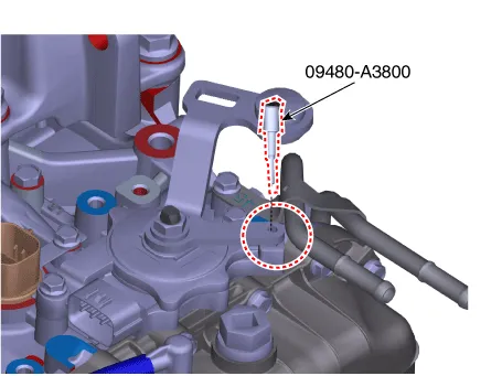
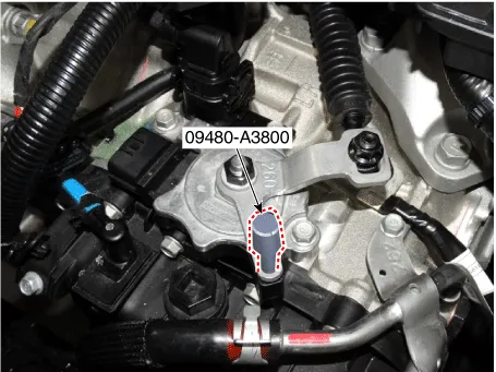
| 4. |
Align the hole in the manual control lever with the "N" position hole of the inhibitor switch and then insert the SST inhibitor switch guide pin (09480-A3800).
|
| 5. |
Tighten the inhibitor switch mounting bolts (A) and manual control lever mounting nut (B) with specified torque.
|
| 6. |
Lightly tighten the nut (A) after installing the shift cable (B).
|
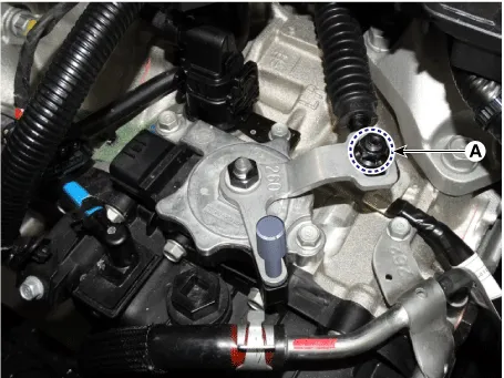
| 7. |
After pushing the nut (A) lightly to direction of arrow to eliminate the free-play, tighten the nut with specified torque.
|
| 8. |
Remove the SST (09480-A3800).
|
| 9. |
Connect the inhibitor switch connector (A).
|

| 10. |
Install the air cleaner assembly. (Refer to Engine Mechanical System - "Air cleaner") |
| 11. |
Check that operating surely at each range of the inhibitor switch corresponding to each position of shift lever. |
Specifications Specification Item Specification Type Hall effect sensor Output voltage (V) High : 1.
Components and components location Component 1. Shift Lever Assembly 2. Shift Cable Assembly Repair procedures Removal 1.
Other information:
Kia Optima DL3 2019-2025 Service and Repair Manual: Integrated Body Control Unit (IBU)
Components and components location Component Location 1. Integrated Body Control Unit (IBU) Schematic diagrams Connector and Terminal Function [Non-Smart key] Pin Function Connector A Connector B
Kia Optima DL3 2019-2025 Service and Repair Manual: Trunk Room Lamp
Repair procedures Removal 1. Disconnect the negative battery terminal. 2. Remove the trunk room lamp (A) by pressing the hook. 3. Disconnect the trunk room lamp connector (A).
Categories
- Manuals Home
- Kia Optima Owners Manual
- Kia Optima Service Manual
- Body Electrical System
- Charging System
- Suspension System
- New on site
- Most important about car
