Kia Optima DL3: Automatic Transaxle Control System / Speed Sensor
Specifications
| Specification |
|
Item |
Specification |
|
Type |
Hall effect sensor |
|
Output voltage (V) |
High : 1.18 - 1.68 |
|
Low : 0.59 - 0.84 |
Description and operation
| Description |
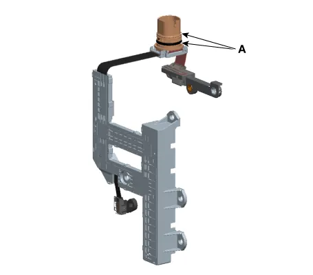
| Input Speed Sensor |
| • |
Input speed sensor (A) and output speed sensor (B) are integrated and installed in the transaxle.
|
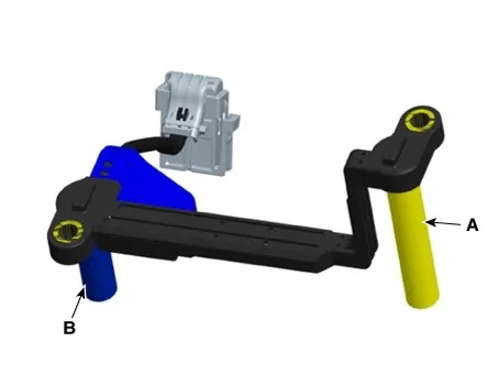
| • |
Speed sensor uses an electric current type hall sensor in which the current is changed by the magnetic variation. |
| • |
The sensor provides critical input data used in feedback control, engine clutch control, gear setting control, line pressure control, clutch activation pressure control, and sensor fault analysis. |
Components and components location
| Components |
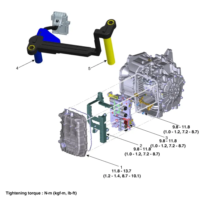
| 1. Valve Body Cover |
4. Output Speed Sensor |
| 2. Main Harness |
5. Input Speed Sensor |
| 3. Valve Body |
Repair procedures
| Inspection |
| 1. |
The automatic transaxle system can be more quickly diagnosed for troubles by using the vehicle diagnostic system (KDS). (Refer to "DTC guide") KDS provides the following information.
|
| Component inspection |
| 1. |
Check the sensor waveform with KDS. |
| Removal |
|

| 1. |
Remove the under cover. (Refer to Engine Mechanical System - "Engine Room Under Cover") |
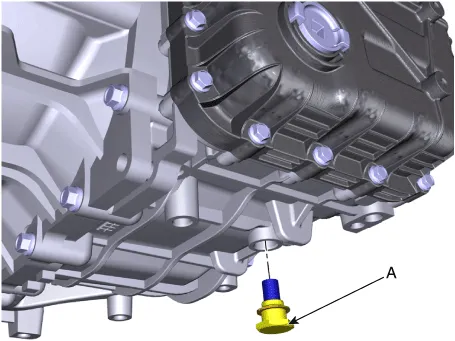
| 2. |
Remove the ATF drain plug (A), allow the fluid to drain out and then reinstall the drain plug.
|
| 3. |
Remove the air cleaner assembly. (Refer to Engine Mechanical System - "Air cleaner") |
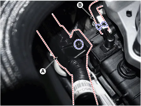
| 4. |
Remove the wiring bracket (A) and the air breather hose (B).
|
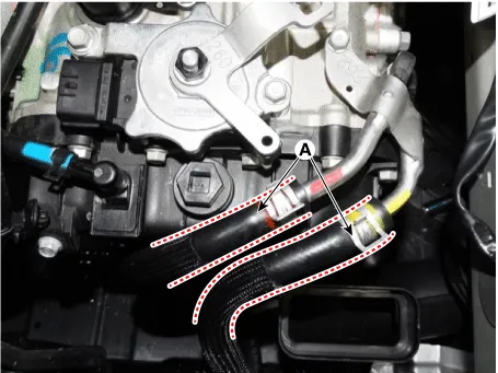
| 5. |
Disconnect the hose (A) after removing the automatic transaxle fluid cooler hose clamp.
|
| 6. |
Lift the vehicle after loosening valve body cover upper bolts. |
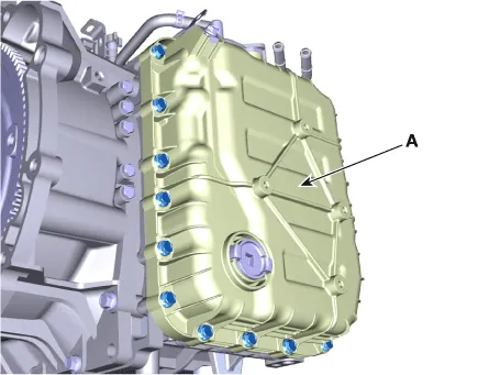
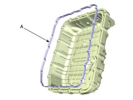
| 7. |
Remove the valve body cover (A) by loosening bolts.
|
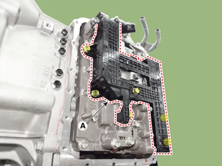
| 8. |
Remove the main harness (A) after removing the bolts.
|
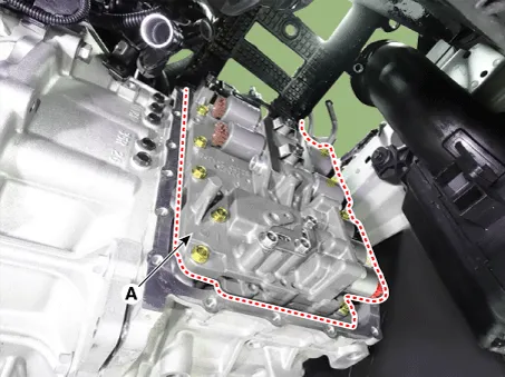
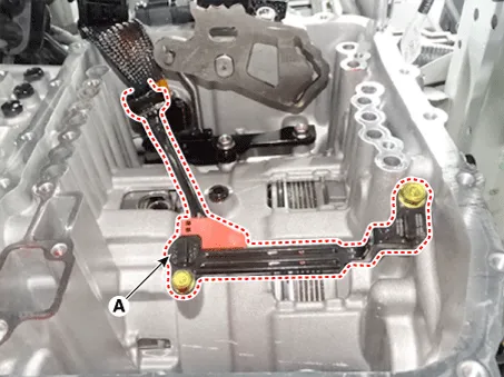
| 9. |
Remove the valve body assembly (A) after loosening the bolts.
|
| 10. |
Disconnect the speed sensor connector (A).
|

| 11. |
Remove the speed sensor (A) after loosening the bolts.
|
| Installation |
| 1. |
Install in the reverse order of removal.
|
Specifications Specification Item Specification Type *NTC thermistor Temp.
Specifications Specification Item Specification Power supply (V) 4.5 - 5.5 V Output type Shifting range (P/R/N/D) Non-contact(2 channel PWM signal) Start, Back-up lamp Contact Description and operation Description • The inhibitor switch mounted on the upper of transaxle and connected with shifter lever.
Other information:
Kia Optima DL3 2019-2026 Service and Repair Manual: License Lamps
Repair procedures Removal 1. Disconnect the negative battery terminal. 2. Remove the lcense lamp (A) by pressing the hook. 3. Disconnect the lcense lamp connector (A).
Kia Optima DL3 2019-2026 Service and Repair Manual: Wiper Arm
Repair procedures Removal 1. If necessary, remove the blade by pushing it in the direction arrow after opening the hook (A). • Move the windshield glass wiper blades to the servic
Categories
- Manuals Home
- Kia Optima Owners Manual
- Kia Optima Service Manual
- Headlamps
- Steering System
- Engine Mechanical System
- New on site
- Most important about car
