Kia Optima DL3: Automatic Transaxle Control System / Shift Lever
Components and components location
| Component |
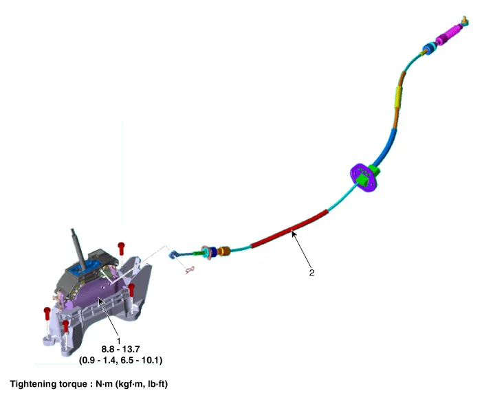
| 1. Shift Lever Assembly |
2. Shift Cable Assembly |
Repair procedures
| Removal |
| 1. |
Shift the gear to "N". |
| 2. |
Remove the floor console assembly. (Refer to Body - "Floor Console Assembly") |
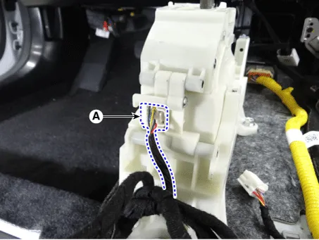
| 3. |
Disconnect the main connector (A).
|
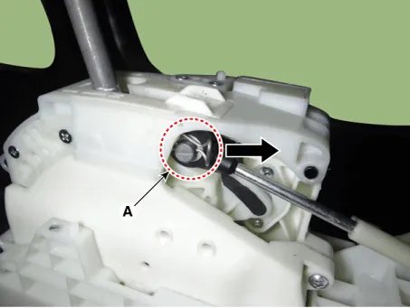
| 4. |
Remove the snap pin (A).
|
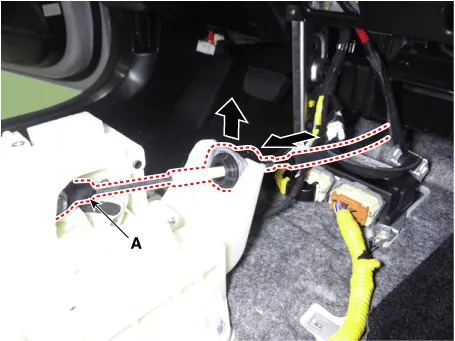
| 5. |
Remove the shift cable (A) from the shift lever.
|
| 6. |
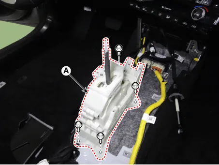
Remove the shift lever assembly (A).
|
| Installation |
| 1. |
Install in the reverse order of removal.
|


Specifications Specification Item Specification Power supply (V) 4.5 - 5.5 V Output type Shifting range (P/R/N/D) Non-contact(2 channel PWM signal) Start, Back-up lamp Contact Description and operation Description • The inhibitor switch mounted on the upper of transaxle and connected with shifter lever.
Components and components location Component 1. Shift Lever Assembly 2. Shift Cable Assembly Repair procedures Removal 1.
Other information:
Kia Optima DL3 2019-2026 Service and Repair Manual: Blower Motor
Repair procedures Inspection 1. Connect the battery voltage and check the blower motor rotation. 2. If the blower motor does not operate well, substitute with a known-good blower motor and check for proper operation.
Kia Optima DL3 2019-2026 Service and Repair Manual: Blower Resistor
Repair procedures Inspection 1. Measure the resistance between the terminals. 2. measured resistance is not within specification, the blower resistor must be replaced. (After removing the resistor) (1) Pin No 1.
Categories
- Manuals Home
- Kia Optima Owners Manual
- Kia Optima Service Manual
- Engine Mechanical System
- Motor Driven Power Steering
- Steering System
- New on site
- Most important about car
