Kia Optima DL3: Intake And Exhaust System / Intake Manifold
Components and components location
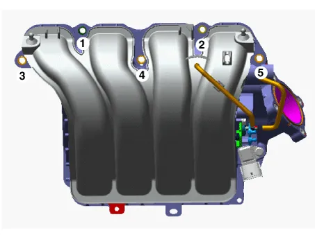
| Components |
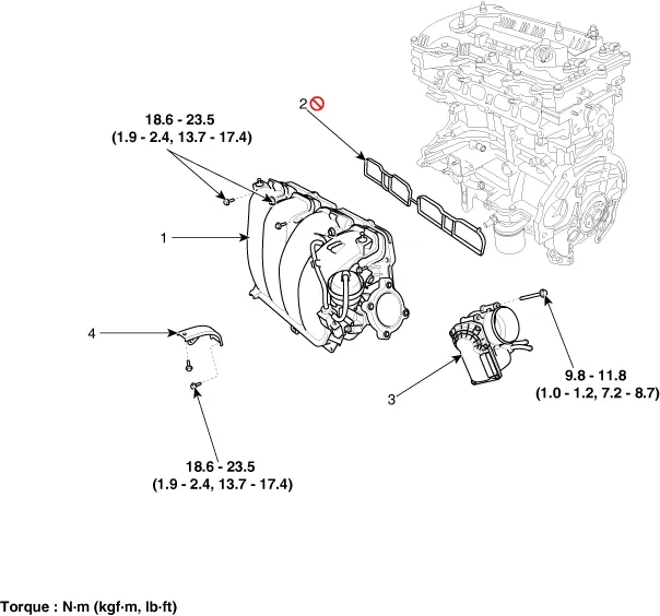
| 1. Intake manifold assembly
2. Intake manifold gasket |
3. Electronic throttle body
4. Intake manifold stay |
Repair procedures
| Removal and Installation |
| 1. |
Remove the engine cover. (Refer to Engine and Transaxle Assembly - "Engine Cover") |
| 2. |
Disconnect the battery negative terminal. |
| 3. |
Remove the air cleaner assembly. (Refer to Intake and Exhaust System - "Air Cleaner") |
| 4. |
Remove the engine room under cover. (Refer to Engine and Transaxle Assembly - "Engine Room Under Cover") |
| 5. |
Disconnect the wiring connectors and harness clamps and remove the wiring protector around the intake manifold.
|
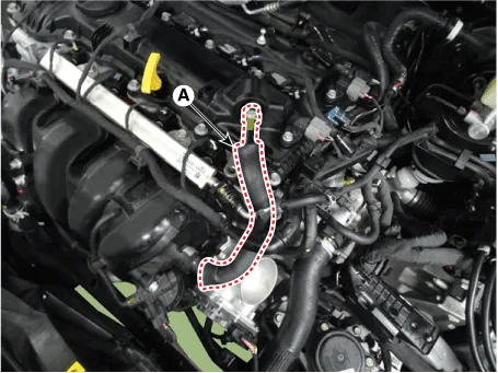
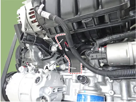
| 6. |
Disconnect the positive crankcase ventilation (PCV) hose (A).
|
| 7. |
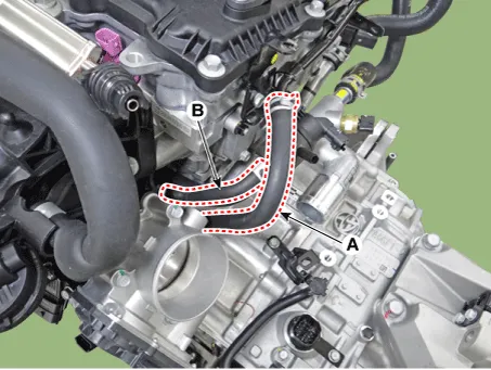
Disconnect the vacuum hose (A) and purge control solenoid valve (PCSV) hose (B).
|
| 8. |
Unfasten the electric throttle body control (ETC) module bolts. (Refer to Engine Control/Fuel System - "ETC (Electric throttle body control) System") |
| 9. |
Remove the intake manifold stay (A).
|
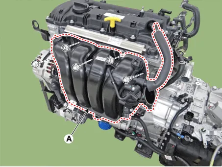
| 10. |
Remove the intake manifold (A) with the gasket.
|

| 11. |
Install in the reverse order of removal. |
Components and components location Components 1. Air duct 2. Air cleaner body 3. Air cleaner element 4. Air cleaner cover 5.
Repair procedures Removal and Installation 1. Disconnect the vacuum hose (A). 2. Remove the variable Intake solenoid (VIS) actuator (B) Tightening torque : 9.
Other information:
Kia Optima DL3 2019-2026 Service and Repair Manual: Heater Unit
Components and components location Component Location 1. Heater unit assembly Compoents 1. Mode control actuator 2. Temperature control actuator [LH] 3. PTC Heater dummy 4.
Kia Optima DL3 2019-2026 Service and Repair Manual: Blower Motor
Repair procedures Inspection 1. Connect the battery voltage and check the blower motor rotation. 2. If the blower motor does not operate well, substitute with a known-good blower motor and check for proper operation.
Categories
- Manuals Home
- Kia Optima Owners Manual
- Kia Optima Service Manual
- Cooling System
- Floor Console Assembly
- Charging System
- New on site
- Most important about car
