Kia Optima DL3: Intake And Exhaust System / Variable Intake Solenoid(VIS) Actuator
Repair procedures
| Removal and Installation |
| 1. |
Disconnect the vacuum hose (A). |
| 2. |
Remove the variable Intake solenoid (VIS) actuator (B)
|
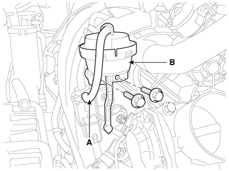
| 3. |
Install in the reverse order of removal. |
Components and components location Components 1. Intake manifold assembly 2. Intake manifold gasket 3. Electronic throttle body 4.
Components and components location Components 1. Heat protector 2. Exhaust manifold gasket 3. Exhaust manifold 4.
Other information:
Kia Optima DL3 2019-2026 Service and Repair Manual: License Lamps
Repair procedures Removal 1. Disconnect the negative battery terminal. 2. Remove the lcense lamp (A) by pressing the hook. 3. Disconnect the lcense lamp connector (A).
Kia Optima DL3 2019-2026 Service and Repair Manual: Heater Core
Repair procedures Replacement 1. Disconnect the negative (-) battery terminal. 2. Remove the heater and blower assembly. (Refer to Heater - "Heater Unit") 3. Loosen the mounting screws and remove the heater core cover (A).
Categories
- Manuals Home
- Kia Optima Owners Manual
- Kia Optima Service Manual
- Headlamps
- Cooling System
- Steering System
- New on site
- Most important about car
