Kia Optima DL3: Intake And Exhaust System / Air Cleaner
Components and components location
| Components |
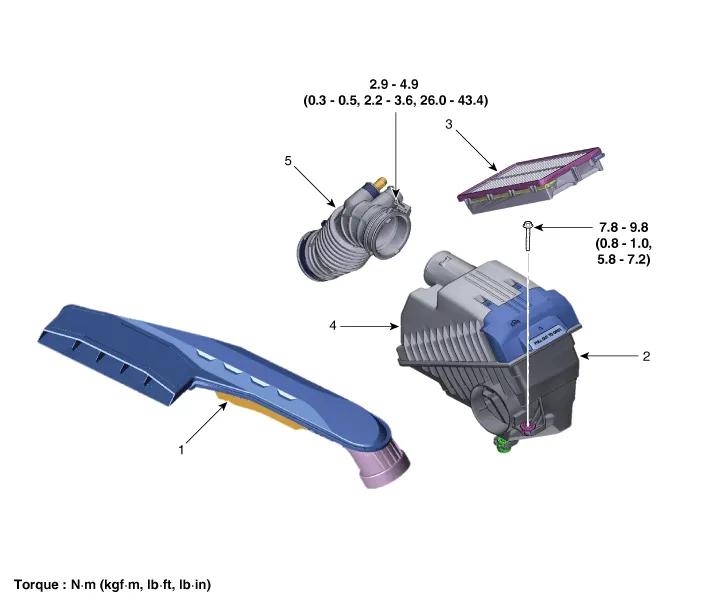
| 1. Air duct 2. Air cleaner body 3. Air cleaner element |
4. Air cleaner cover 5. Air intake hose |
Repair procedures
| Removal and Installation |
Air Cleaner Assembly
| 1. |
Disconnect the battery negative terminal. |
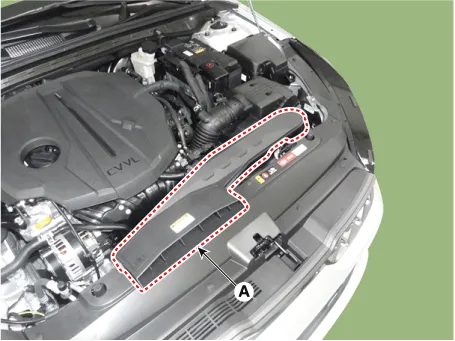
| 2. |
Remove the air duct (A).
|
| 3. |
Remove the engine cover. (Refer to Engine and Transaxle Assembly - "Engine Cover") |
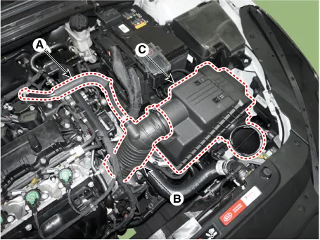
| 4. |
Remove the air cleaner assembly.
|
| 5. |
Install in the reverse order of removal. |
Air cleaner element replacement
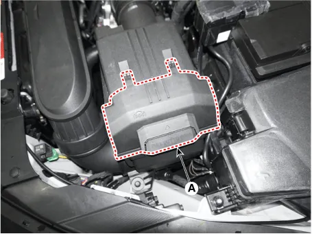
| 1. |
Remove the air cleaner element cover (A) by lifting it off.
|
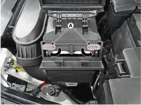
| 2. |
Release the element locking by turning the levers to "UNLOCK" position and then pull out the element forward.
|
| 3. |
Replace the air cleaner element (A) with a new one.
|


| 4. |
Fully insert the element into the air cleaner and then close the element cover (A) after turning the levers to "LOCK" position.
|
| Inspection |
| 1. |
Remove the air cleaner element. |
| 2. |
Check if the air filter is excessively dirty. If so, replace the air cleaner element. |
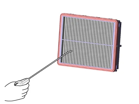
| 3. |
If the air cleaner element needs to be cleaned, blow compressed air as shown in the illustration to clean it.
|
| 4. |
Reinstall the air cleaner element. |
Components and components location Components 1. Intake manifold assembly 2. Intake manifold gasket 3. Electronic throttle body 4.
Other information:
Kia Optima DL3 2019-2026 Service and Repair Manual: Power Windows
Components and components location Component Location 1. Power window main switch 2. Rear window main switch 3. Front power window motor 4. Rear power window motor Description and operation Description Power Window Safety Function When the driver or passenger p
Kia Optima DL3 2019-2026 Service and Repair Manual: In-car Sensor
Description and operation Description The In-car air temperature sensor is built in the heater & A/C control unit. The sensor contains a thermistor which measures the temperature of the inside. The signal decided by the resistance value which changes in accordance with perceived inside temperature, is delivered to heater co
Categories
- Manuals Home
- Kia Optima Owners Manual
- Kia Optima Service Manual
- Rear Brake Disc
- Floor Console Assembly
- Engine Control / Fuel System
- New on site
- Most important about car
