Kia Optima DL3: Brake System / Brake Pedal
Components and components location
| Components |
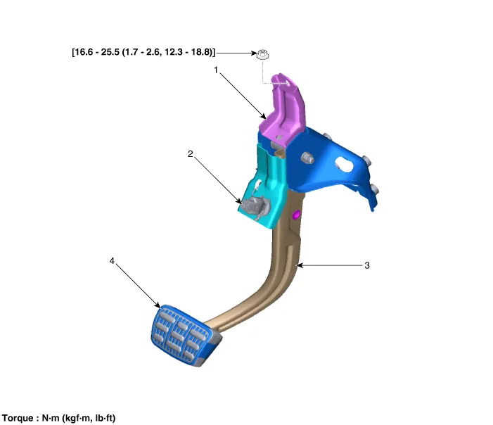
| 1. Brake member assembly 2. Stop lamp switch |
3. Brake pedal arm assembly
4. Brake pedal pad |
Repair procedures
| Removal |
| 1. |
Turn ignition switch OFF and disconnect the negative (-) battery cable. |
| 2. |
Remove the crash pad lower panel. (Refer to Body - "Crash Pad Lower Panel") |
| 3. |
Remove the drive airbag module. (Refer to Restraint - "Drive Airbag Module") |
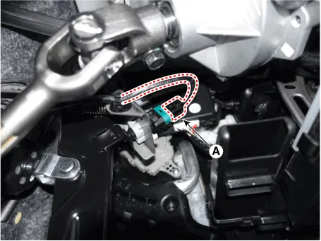
| 4. |
Disconnect the stop lamp switch connector (A).
|
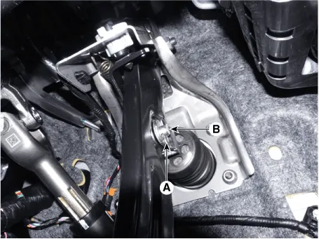
| 5. |
Separate the snap pin (A) and clevis pin (B).
|
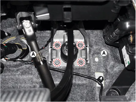
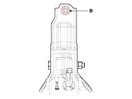
| 6. |
Loosen the nuts (A), (B) and then remove the brake pedal assembly.
|
| Inspection |
| 1. |
Check the brake pedal for bending or twisting. |
| 2. |
Check the brake pedal return spring for damage. |
| 3. |
Check the stop lamp switch. (Refer to Brake System - "Stop Lamp Switch") |
| Installation |
| 1. |
Install in the reverse order of removal.
|

Components and components location Components 1. HECU flare nuts. 2. HECU to body mounting nuts. 3. Master cylinder to HECU flare nut.
Components and components location Components 1. Brake member assembly 2. Stop lamp switch 3. Brake pedal arm assembly 4.
Other information:
Kia Optima DL3 2019-2026 Service and Repair Manual: Power Windows
Components and components location Component Location 1. Power window main switch 2. Rear window main switch 3. Front power window motor 4. Rear power window motor Description and operation Description Power Window Safety Function When the driver or passenger p
Kia Optima DL3 2019-2026 Service and Repair Manual: Wiper Arm
Repair procedures Removal 1. If necessary, remove the blade by pushing it in the direction arrow after opening the hook (A). • Move the windshield glass wiper blades to the servic
Categories
- Manuals Home
- Kia Optima Owners Manual
- Kia Optima Service Manual
- Timing Chain
- Automatic Transaxle System
- Body Electrical System
- New on site
- Most important about car
