Kia Optima DL3: Brake System / Brake Line
Components and components location
| Components |
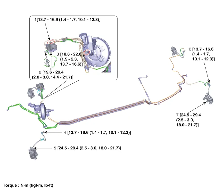
| 1. HECU flare nuts. 2. HECU to body mounting nuts. 3. Master cylinder to HECU flare nut. 4. Front brake line tube flare nut. |
5. Front brake line to brake
hose. 6. Rear brake line tube flare nut. 7. Rear brake line to brake hose. |
Repair procedures
| Removal |
Be careful not to damage the parts located under the vehicle (floor under cover, fuel filter, fuel tank and canister) when raising the vehicle using the lift. (Refer to General Information - "Lift and Support Points") |

Brake Tube [Engine Room]
| 1. |
Disconnect the brake fiuid level switch connector, and remove the reservoir cap. |
| 2. |
Remove the brake fluid from the master cylinder reservior with a syringe.
|
| 3. |
Remove the brake tube after loosening the flare nuts from the ESC, master cylinder and brake tube connector.
|
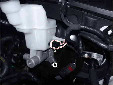
Brake Hose
| 1. |
Disconnect the brake fluid level sensor connector (A).
|

| 2. |
Remove the brake fluid from the master cylinder reservoir with a syringe.
|
| 3. |
Remove the front wheel and tire. (Refer to Tires/Wheels - "Wheel") |
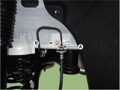
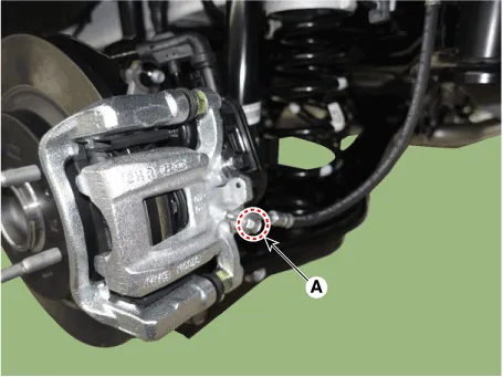
| 4. |
Remove the tube flare nut (A). |
| 5. |
Loosen the brake hose bracket bolt (B).
[Front]
[Rear]
|

| 6. |
Loosen the mounting bolt (A) and then remove the brake hose bracket from the strut assembly.
|
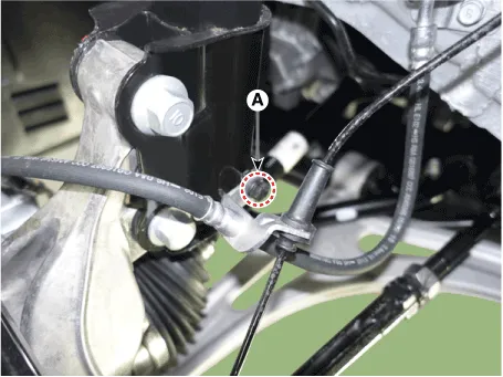
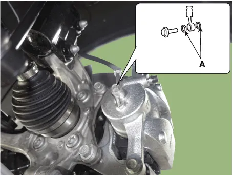
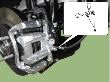
| 7. |
Remove the hose after loosening the brake hose bolt (A) from the caliper.
[Front]
[Rear]
|

| Inspection |
| 1. |
Check the brake tubes for cracks, crimps and corrosion. |
| 2. |
Check the brake tube flare nuts for damage and fluid leakage. |
| Installation |
| 1. |
Install in the reverse order of removal.
|
| 2. |
After installation, bleed the brake system. (Refer to Brake System - "Brake Bleeding Prcoedures") |
Components and components location Components 1. Reservoir cap 2. Reservoir 3. Master cylinder 4. Brake fluid level sensor Repair procedures Removal 1.
Components and components location Components 1. Brake member assembly 2. Stop lamp switch 3. Brake pedal arm assembly 4.
Other information:
Kia Optima DL3 2019-2026 Service and Repair Manual: Temperature Control Actuator
Components and components location Components Location 1. Temperature control actuator [LH] 2. Temperature control actuator [RH] Description and operation Description The temperature control actuator is located at the heater unit.
Kia Optima DL3 2019-2026 Service and Repair Manual: Intake Actuator
Components and components location Components Location 1. Intake actuator Description and operation Description The intake actuator is located at the blower unit. It regulates the intake door by a signal from the control unit.
Categories
- Manuals Home
- Kia Optima Owners Manual
- Kia Optima Service Manual
- Suspension System
- Floor Console Assembly
- Steering System
- New on site
- Most important about car
