Kia Optima DL3: Wiper/Washer / Wiper Arm
Repair procedures
| Removal |
| 1. |
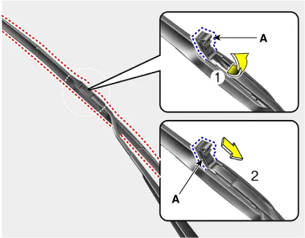
If necessary, remove the blade by pushing it in the direction arrow after opening the hook (A).
|

| 2. |
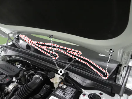
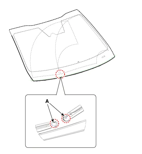
Remove the wiper arms (A) by loosening the nuts after removing the caps.
|
| Installation |
| 1. |
Install in the reverse order of removal.
|

Schematic diagrams Connector and Terminal Function Pin Function 1 Ground (-) 2 Parking 3 Power (+) 4 Low 5 High Repair procedures Removal 1.
Other information:
Kia Optima DL3 2019-2026 Service and Repair Manual: Headlamps
Components and components location Component Location 1. Low beam 2. High beam 3. Daytime Running Light / Position lamp 4. Low assist beam 5. Turn signal lamp Schematic diagrams Connector and Terminal Function Connector Terminal Function
Kia Optima DL3 2019-2026 Service and Repair Manual: Heated Seats Only
Components and components location Components Front Seat Heater 1. Front seat back heater 2. Front seat cushion heater 3. Front seat heater unit / ventilation unit Rear Seat Heater 1.
Categories
- Manuals Home
- Kia Optima Owners Manual
- Kia Optima Service Manual
- Body Electrical System
- Automatic Transaxle System
- Cooling System
- New on site
- Most important about car
