Kia Optima DL3: Cylinder Head Assembly / Cylinder Head
Components and components location
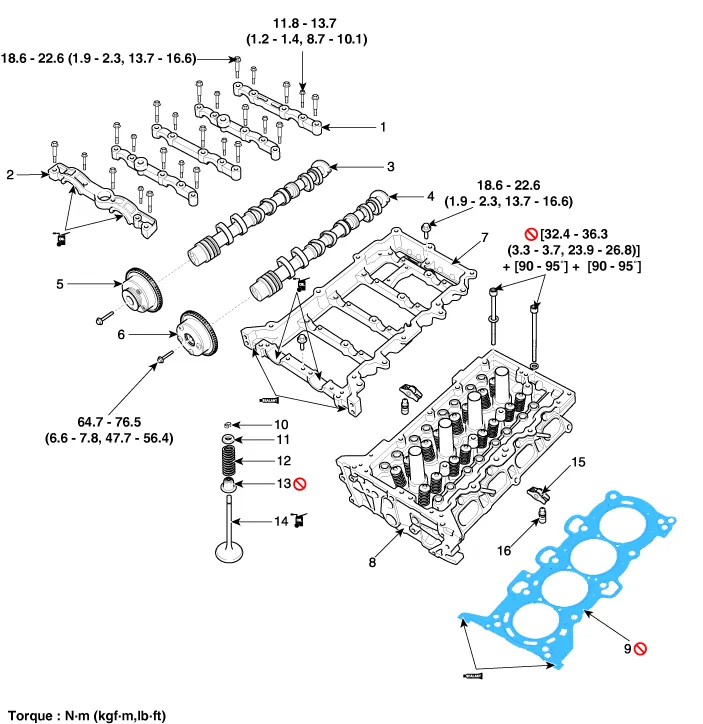
| Components |
|
1. Camshaft bearing cap 2. Camshaft front bearing cap 3. Exhaust camshaft 4. Intake camshaft 5. Exhaust CVVT assembly 6. Intake CVVT assembly |
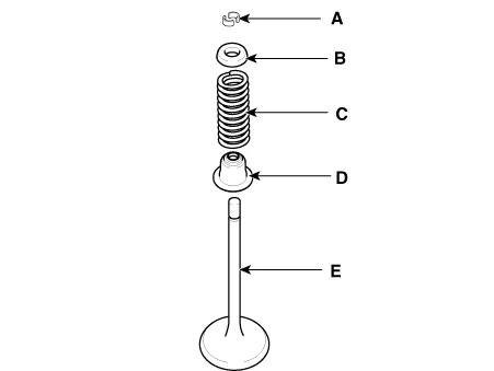
7. Cam carrier 8. Cylinder head 9. Cylinder head gasket 10. Retainer lock 11. Retainer 12. Valve spring |
13. Valve stem seal 14. Valve 15. Swing arm 16. Hydraulic lash adjuster (HLA) |
Repair procedures
| Removal |
Engine removal is not required for this procedure.
|

|

| 1. |
Remove the Battery. (Refer to Engine Electrical System - “Battery”) |
| 2. |
Remove the air cleaner assembly. (Refer to Intake and Exhaust System - “Air Cleaner”) |
| 3. |
Remove the battery tray. (Refer to Engine Electrical System - “Battery”) |
| 4. |
Remove the engine room under cover. (Refer to Engine and Transaxle Assembly - “Engine Room Under Cover”) |
| 5. |
Drain the coolant. (Refer to Cooling System - “Coolant”) |
| 6. |
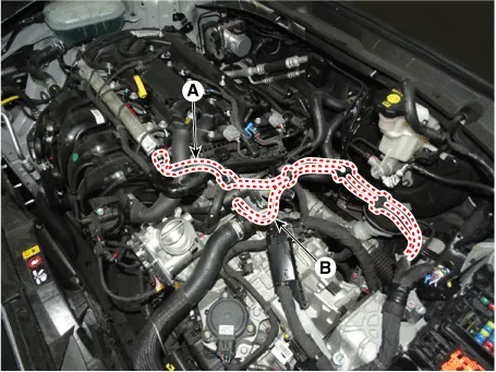
Disconnect the fuel hose (A) and purge control solenoid valve (PCSV) hose (B).
|
| 7. |
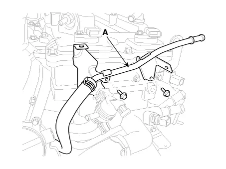
Remove the vacuum pipe (A).
|
| 8. |
Remove the condenser (A).
|
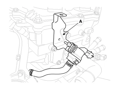
| 9. |
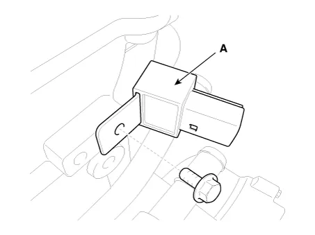
Remove the purge control solenoid valve (PCSV) bracket (A).
|
| 10. |
Remove the delivery pipe. (Refer to Engine Control/Fuel System - “Delivery Pipe”) |
| 11. |
Remove the cylinder head cover. (Refer to Cylinder Head Assembly - “Cylinder Head Cover”) |
| 12. |
Remove the timing chain. (Refer to Timing System - “Timing Chain”) |
| 13. |
Remove the exhaust manifold. (Refer to Intake and Exhaust System - “Exhaust Manifold”) |
| 14. |
Remove the intake manifold. (Refer to Intake and Exhaust System - “Intake Manifold”) |
| 15. |
Remove the water temperature control assembly. (Refer to Cooling System - “Water Temperature Control Assembly”) |
| 16. |
Remove the heater pipe. (Refer to Cooling System - "Thermostat") |
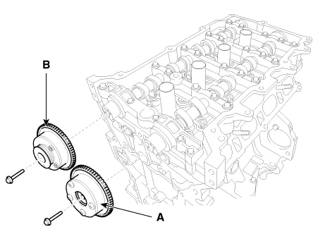
| 17. |
Remove the intake CVVT assembly (A) and exhaust CVVT assembly (B).
|
| 18. |
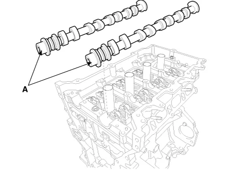
Remove the camshaft.
|
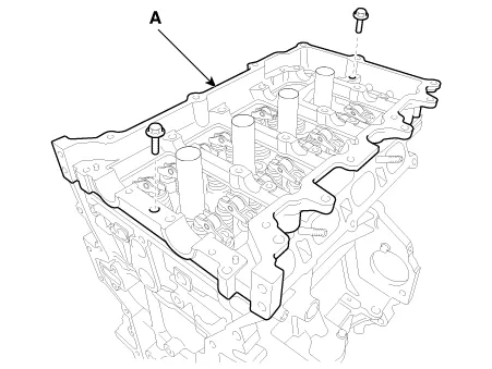
| 19. |
Remove the cam carrier (A).
|
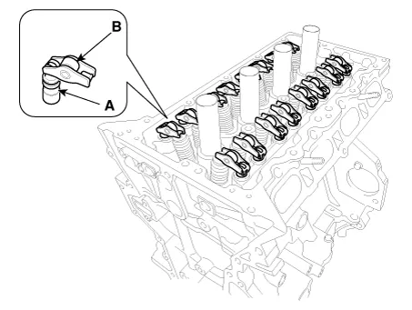
| 20. |
Remove the hydraulic lash adjuster (HLA) (A) and the swing arm (B).
|
| 21. |
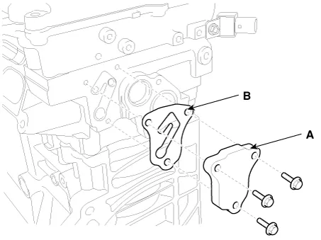
Remove the oil control adapter (A) with the gasket (B).
|
| 22. |
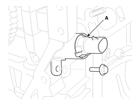
Remove the intake oil control valve (OCV) (A).
|
| 23. |
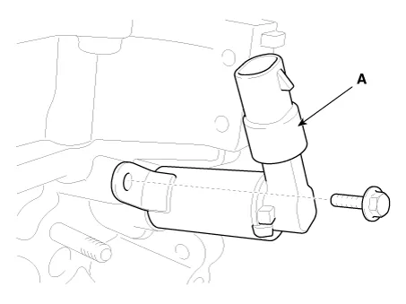
Remove the exhaust oil control valve (OCV) (A).
|
| 24. |
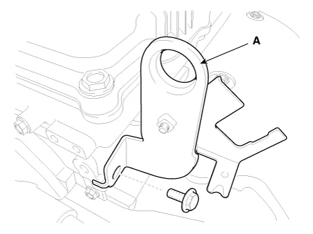
Remove the rear engine hanger (A).
|
| 25. |
Remove the spark plugs. (Refer to Engine Electrical System - “Spark Plug”) |
| 26. |
Remove the cylinder head.
|
| Disassembly |
Identify, valves and valve springs as they are removed so that each item can be reinstalled in its original position. |
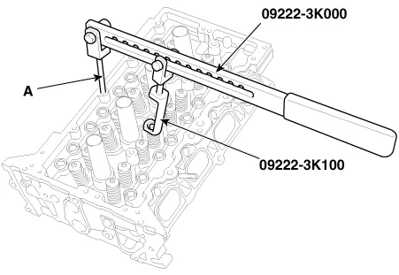
| 1. |
Remove the valves.
|
| Inspection |
Cylinder Head
| 1. |
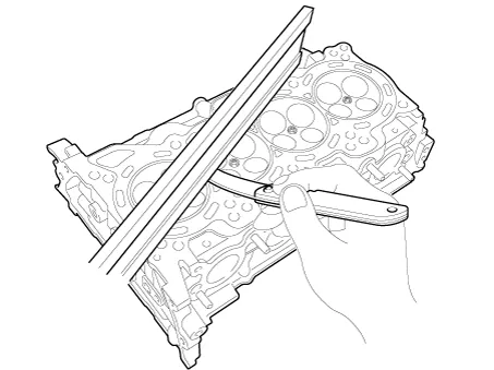
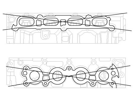
Inspect for flatness.
Using a precision straight edge and feeler gauge, measure the contacting surface of the cylinder block and the manifolds for warpage. If the flatness is greater than maximum, replace the cylinder head.
|
| 2. |
Inspect for cracks. Check the combustion chamber, intake ports, exhaust ports and cylinder block surface for cracks. If cracked, replace the cylinder head. |
Valve And Valve Spring
| 1. |
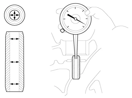
Inspect valve stems and valve guides.
|
| 2. |
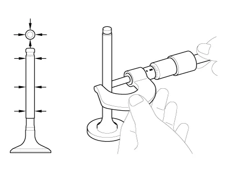
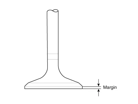
Inspect the valves.
|
| 3. |
Inspect the valve seats and the valve guides.
|
| 4. |
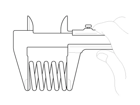
Inspect the valve springs.
|
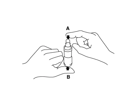
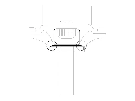
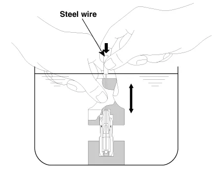
Hydraulic Lash Adjuster (HLA)
With the HLA filled with engine oil, hold A and press B by hand.
If B moves, replace the HLA.
|
Problem |
Possible cause |
Action |
||||
|
1. Temporary noise when starting a cold engine |
Normal |
This noise will disappear after the oil in the engine reaches the normal
pressure. |
||||
|
2. Continuous noise when the engine is started after parking more than 48
hours |
Oil leakage of the high pressure chamber on the HLA, allowing air to get
in |
Noise will disappear within 15 minutes when engine runs at 2000-3000 rpm. If it doesn’t disappear, refer to step 7 below. |
||||
|
3. Continuous noise when the engine is first started after rebuilding cylinder
head |
Insufficient oil in cylinder head oil gallery |
|||||
|
4. Continuous noise when the engine is started after excessively cranking
the engine by the starter motor or band |
|
|||||
|
5. Continuous noise when the engine is running after changing the HLA |
|
|||||
|
6. Continuous noise during idle after high engine speed |
Engine oil level too high or too low |
|
||||
|
Excessive amount of air in the oil at high engine speed |
Check oil supply system. |
|||||
|
Deteriorated oil |
Check oil quality. If deteriorated, replace with specified type. |
|||||
|
7. Noise continues for more than 15 minutes |
Low oil pressure |
Check oil pressure and oil supply system of each part of engine. |
||||
|
Faulty HLA |
Remove the cylinder head cover and press HLA down by hand. If it moves, replace the HLA. |
| Reassembly |
|
| 1. |
Install the valves.
|
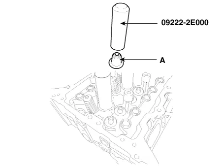
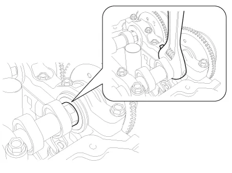
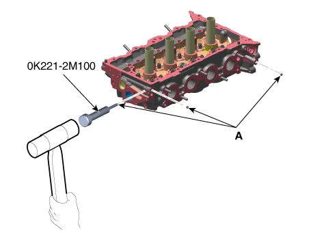
| 2. |
Check if the steel ball (A) is installed in the cylinder head when replacing the cylinder head.
|
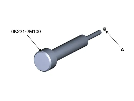
| 3. |
If steel ball not installed, be sure to install the steel ball.
|
| Installation |
|
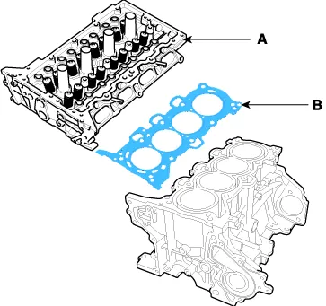
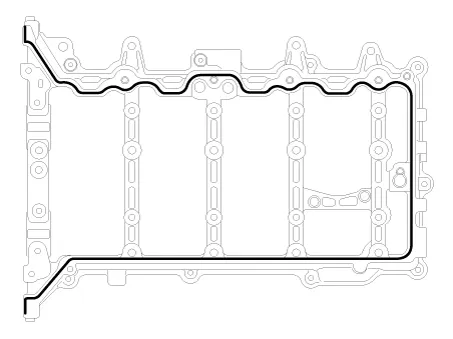
| 1. |
Install the cylinder head gasket (B) on the cylinder block.
|
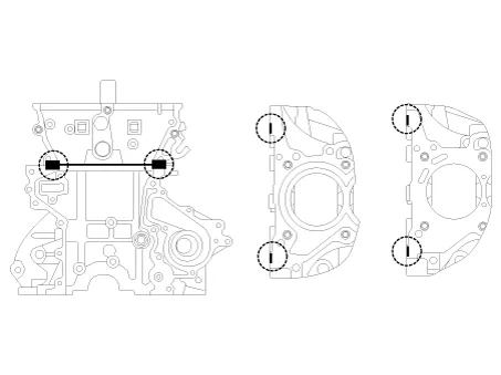
| 2. |
Place the cylinder head (A) carefully to protect damage to the head gasket (B) during installation.
|
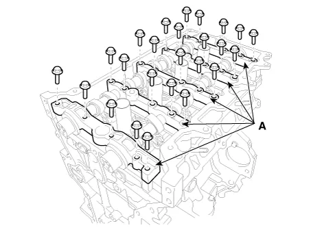
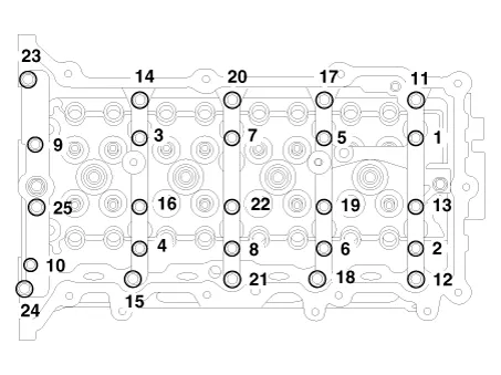
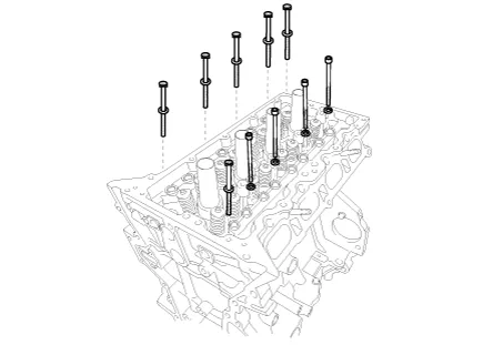
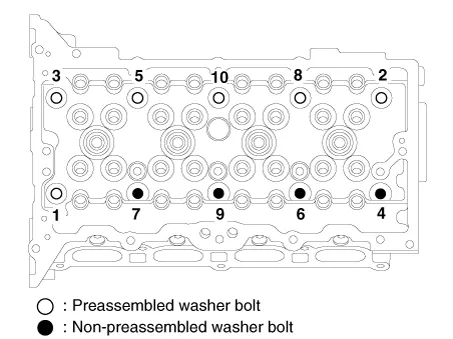
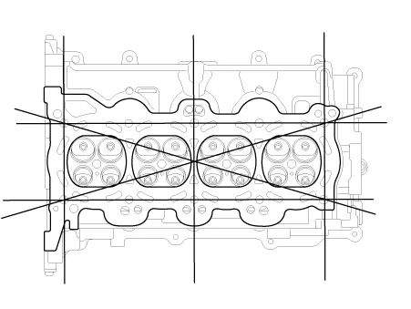
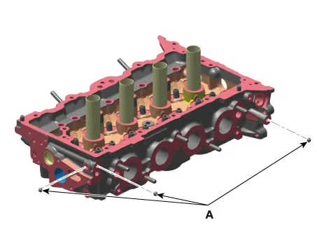
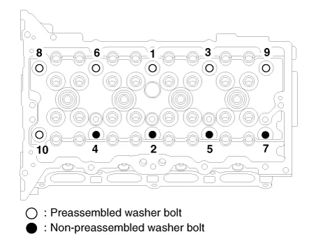
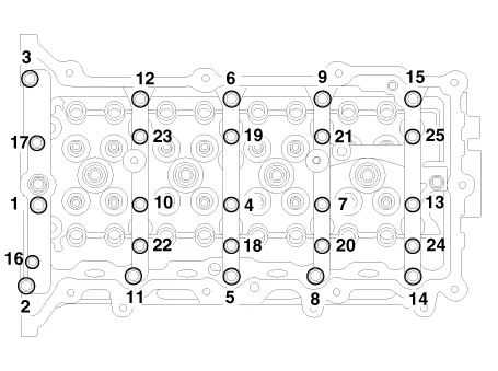
| 3. |
Install the cylinder head bolts with washers. Using SST (09221-4A000), install and tighten the 10 cylinder head bolts, in several passes, in the sequence as shown.
|
| 4. |
Install the rear engine hanger (A).
|
| 5. |
Install the exhaust oil control valve (OCV) (A).
|
| 6. |
Install the intake oil control valve (OCV) (A).
|

| 7. |
Install the oil control adapter (A) with a new gasket (B).
|
| 8. |
Install the hydraulic lash adjuster (HLA)(A) and the swing arm (B).
|
| 9. |
Install the cam carrier.
|
| 10. |
Install the camshafts.
|
| 11. |
Install the intake CVVT assembly (A) and exhaust CVVT assembly (B).
|
| 12. |
Install the other parts reverse order of removal. |
| 13. |
Add all the necessary fluids and check for leaks. Connect KDS. Check for codes, note, and clear. Recheck. |
|
Components and components location Components 1. Camshaft bearing cap 2. Camshaft front bearing cap 3. Exhaust camshaft 4.
Other information:
Kia Optima DL3 2019-2026 Service and Repair Manual: Ambient Temperature Sensor
Description and operation Description The ambient temperature sensor is located at the front of the condenser and detects ambient air temperature. It is a negative type thermistor; resistance will increase with lower temperature, and decrease with higher temperature.
Kia Optima DL3 2019-2026 Service and Repair Manual: Temperature Control Actuator
Components and components location Components Location 1. Temperature control actuator [LH] 2. Temperature control actuator [RH] Description and operation Description The temperature control actuator is located at the heater unit.
Categories
- Manuals Home
- Kia Optima Owners Manual
- Kia Optima Service Manual
- Body Electrical System
- Cooling System
- Engine Control / Fuel System
- New on site
- Most important about car
