Kia Optima DL3: Chassis / Disc Brakes and Pads
Repair procedures
| Inspection |
Check the pads for excessive wear, discs for run out and wear, and calipers for fluid leakage.
| Front Brake |
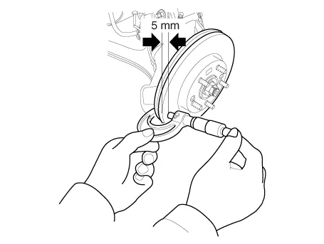
Front Brake Disc Thickness Check
| 1. |
Check the brake disc for damage and cracks. |
| 2. |
Remove all rust and contamination from the surface, and measure the disc thickness at 8 points, at least, of same distance (5mm) from the brake disc outer circle.
|
| 3. |
If wear exceeds the limit, replace the discs and pad assembly left and right of the vehicle. |
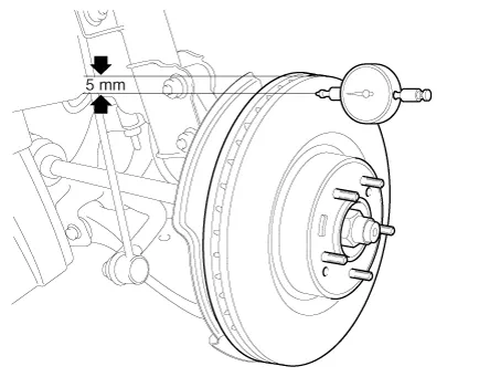
Front Brake Disc Runout Check
| 1. |
Place a dial gauge about 5mm (0.20 in) from the outer circumference of the brake disc, and measure the runout of the disc.
|
| 2. |
If the runout of the brake disc exceeds the limit specification, replace the disc, and then measure the runout again. |
| 3. |
If the runout does not exceed the limit specification, install the brake disc after turning it 180° and then check the runout of the brake disc again. |
| Rear Brake |
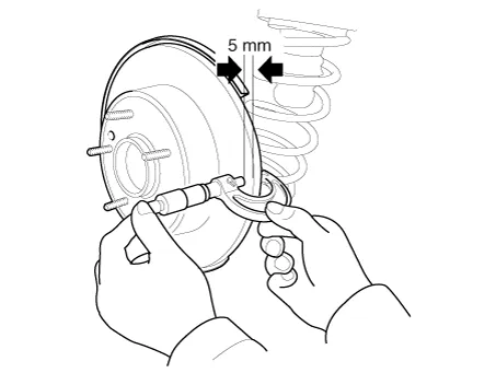
Rear Brake Disc Thickness Check
| 1. |
Check the brake disc for damage and cracks. |
| 2. |
Remove all rust and contamination from the surface, and measure the disc thickness at 8 points, at least, of same distance (5mm) from the brake disc outer circle.
|
| 3. |
If wear exceeds the limit, replace the discs and pad assembly left and right of the vehicle. |
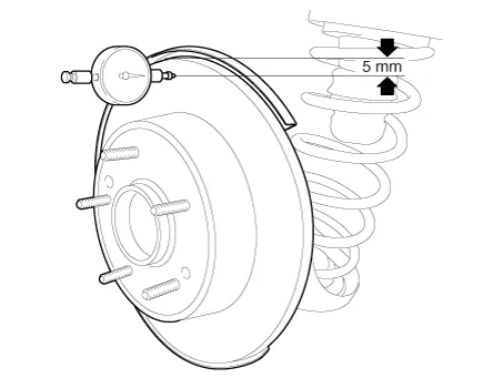
Rear Brake Disc Runout Check
| 1. |
Place a dial gauge about 5mm (0.20 in.) from the outer circumference of the brake disc, and measure the runout of the disc.
|
| 2. |
If the runout of the brake disc exceeds the limit specification, replace the disc, and then measure the runout again. |
| 3. |
If the runout cannot be corrected by changing the position of the brake disc, replace the brake disc. |
Brake Pad Check
| 1. |
Check the pad wear. Measure the pad thickness and replace it, if it is less than the specified value.
|
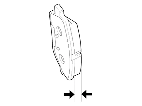
| 2. |
Check that grease is applied to sliding contact points and check the pad and backing metal for damage. |
Repair procedures Inspection Visually check for proper installation, chafing, cracks, deterioration and any leakage. Replace any deteriorated or damaged parts immediately.
Repair procedures Inspection Check whether the stroke is within specification when the parking brake lever is depressed with 44 lbf, 196 N(20 kgf) of force.
Other information:
Kia Optima DL3 2019-2026 Service and Repair Manual: Hazard Lamp Switch
Schematic diagrams Connector and Terminal Function Repair procedures Removal 1. Disconnect the negative battery terminal. 2. Remove the crash pad garnish [RH]. (Refer to Body - "Crash Pad Garnish") 3.
Kia Optima DL3 2019-2026 Service and Repair Manual: Power Window Motor
Schematic diagrams Circuit Diagram [Safety Window Motor] [Standard Window Motor] Repair procedures Inspection Front Power Window Motor 1. Disconnect the negative battery terminal. 2.
Categories
- Manuals Home
- Kia Optima Owners Manual
- Kia Optima Service Manual
- Automatic Transaxle System
- Engine Mechanical System
- Restraint
- New on site
- Most important about car
