Kia Optima DL3: Drive Belt System / Drive Belt Tensioner
Components and components location
| Components |
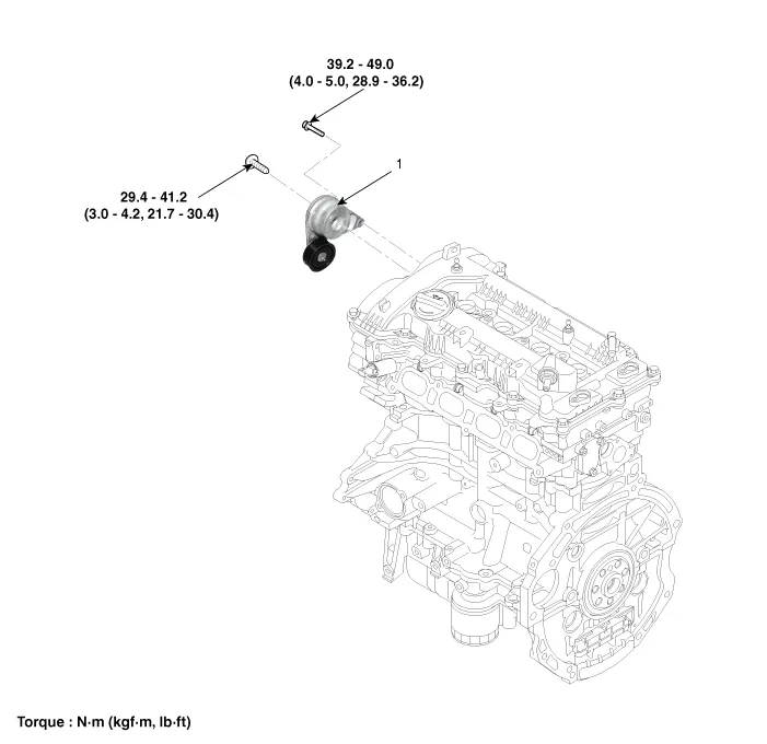
| 1. Drive belt tensioner |
Repair procedures
| Removal and Installation |
| 1. |
Remove the drive belt. (Refer to Drive Belt System - "Drive Belt") |
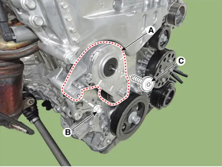
| 2. |
Remove the drive belt tensioner (A).
|
| 3. |
Install in the reverse order of removal. |
Repair procedures Removal and Installation 1. Remove the engine room under cover. (Refer to Engine and Transaxle Assembly - "Engine Room Under Cover") 2.
Repair procedures Removal and Installation 1. Remove the drive belt. (Refer to Drive Belt System - "Drive Belt") 2.
Other information:
Kia Optima DL3 2019-2026 Service and Repair Manual: Ambient Temperature Sensor
Description and operation Description The ambient temperature sensor is located at the front of the condenser and detects ambient air temperature. It is a negative type thermistor; resistance will increase with lower temperature, and decrease with higher temperature.
Kia Optima DL3 2019-2026 Service and Repair Manual: Heater Control Unit
Components and components location Components Connector Pin Function [Connector A] Pin NO Funtion Pin NO Funtion 1 Ground 11 Ground 2 Clean signal 12 -
Categories
- Manuals Home
- Kia Optima Owners Manual
- Kia Optima Service Manual
- Automatic Transaxle System
- Rear Brake Disc
- Headlamps
- New on site
- Most important about car
