Kia Optima DL3: Fuses And Relays / Engine Room Junction Block
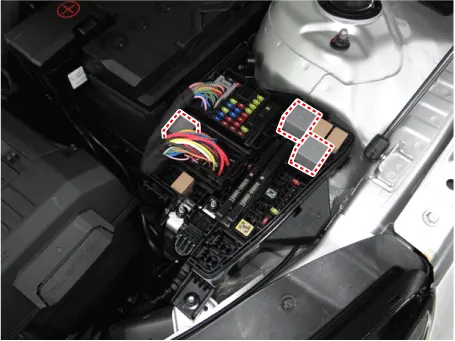
Components and components location
| Components Location |
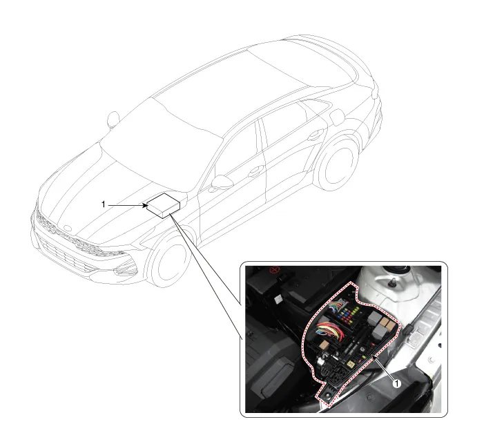
| 1. Engine room junction block
|
Repair procedures
| Inspection |
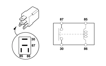
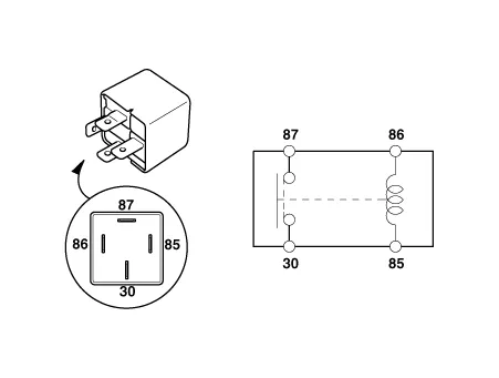
Power Relay (Type A)
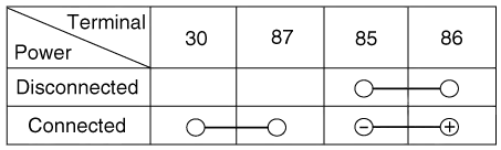
Check for continuity between the terminals.
| 1. |
After supplying power between No. 85 and 86 power relay terminals, check that there is continuity between No. 30 and 87 terminals. |
| 2. |
After disconnecting power between No. 85 and 86 power relay terminals, check that there is no continuity between No. 30 and 87 terminals.
|
Power Relay (Type B)
Check for continuity between the terminals.
| 1. |
After supplying power between No. 85 and 86 power relay terminals, check that there is continuity between No. 30 and 87 terminals. |
| 2. |
After disconnecting power between No. 85 and 86 power relay terminals, check that there is no continuity between No. 30 and 87 terminals.
|

Fuse
| 1. |
Check that the fuse holders are loosely held and that the fuses are securely fixed by the holders. |
| 2. |
Check that each fuse circuit has the exact fuse capacity. |
| 3. |
Check the fuses for any damage.
|

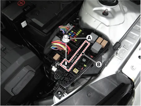
Multi Fuse
| 1. |
Disconnect the negative battery terminal. |
| 2. |
Loosen the multi fuse mounting nut (A). |
| 3. |
Remove the multi fuses (B) by releasing the hook.
|
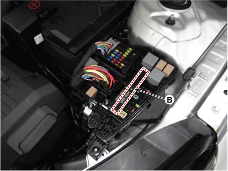
| 4. |
Check the multi fuses for any damage.
|

| Removal |
Engine Room PCB Block
| 1. |
Disconnect the negative battery terminal. |
| 2. |
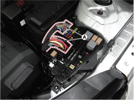
Disconnect the connector (A).
|
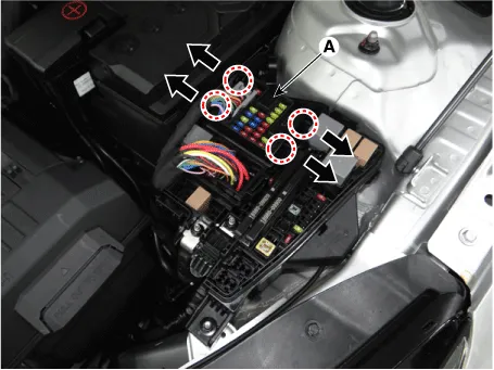
| 3. |
Push the hooks in the direction of the arrow and lift up the engine room PCB block (A).
|
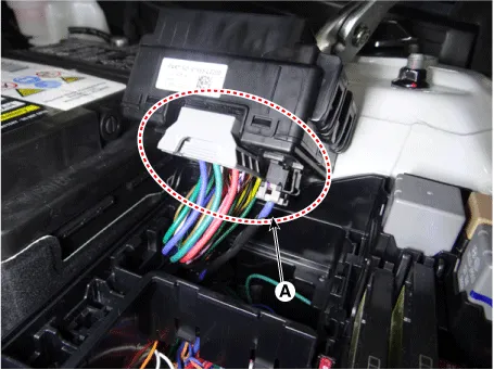
| 4. |
Disconnect the connectors (A) from the engine room PCB block.
|
| Installation |
| 1. |
Install in the reverse order of removal. |
Components and components location Component Location 1. Integrated central control unit (ICU) Description and operation Description Integrated Central control Unit (ICU) combines both Smart Junction Block (SJB) and Integrated Gateway & Power Control Module (IGPM) System Block Diagram Function Item Function Function Switch input Receives switch inputs and then sends the switch status to each module through CAN message.
Other information:
Kia Optima DL3 2019-2026 Service and Repair Manual: Room Lamp
Repair procedures Removal When removing with a flat-tip screwdriver or remover, wrap protective tape around the tools to prevent damage to components. 1.
Kia Optima DL3 2019-2026 Service and Repair Manual: Power Door Locks
C
Categories
- Manuals Home
- Kia Optima Owners Manual
- Kia Optima Service Manual
- Timing Chain
- Battery
- Engine Mechanical System
- New on site
- Most important about car
