
Kia Optima DL3: Front Door / Front Door Trim
Components and components location
| Component Location |
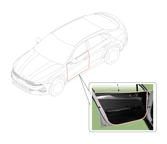
| 1. Front door trim |
Repair procedures
| Replacement |
|

| 1. |
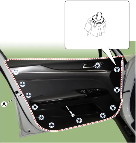
Loosen the mounting screw and remove the front door trim (A).
|
| 2. |
Remove the front door inside handle cage (A).
|


| 3. |
Disconnect the connectors (A).
|

| 4. |
To install, reverse the removal procedure.
|
Components and components location Components 1. Front door trim 2. Front door belt inside weatherstrip 3. Front door module 4.
Components and components location Component Location 1. Front door window glass Repair procedures Replacement • When removing with a flat-tip screwdriver or remover, wrap protective tape around the tools to prevent damage to components.
Other information:
Kia Optima DL3 2019-2026 Service and Repair Manual: Power Door Mirror Switch
Schematic diagrams Connector and Terminal Function Pin Function 1 B-CAN (Low) 2 B-CAN (High) 3 Ground (Assist safety) 4 Assist safety 5 LIN (For IMS)
Kia Optima DL3 2019-2026 Service and Repair Manual: Heater Unit
Components and components location Component Location 1. Heater unit assembly Compoents 1. Mode control actuator 2. Temperature control actuator [LH] 3. PTC Heater dummy 4.
Categories
- Manuals Home
- Kia Optima Owners Manual
- Kia Optima Service Manual
- Lift And Support Points
- Engine Mechanical System
- Body Electrical System
- New on site
- Most important about car
