Kia Optima DL3: Driveshaft Assembly / Front Driveshaft
Components and components location
| Components |
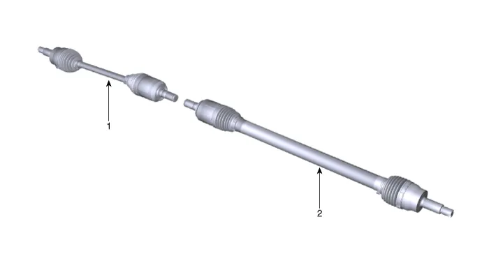
| 1. Front driveshaft (LH) |
2. Front driveshaft (RH) |
Repair procedures
| Removal |
| 1. |
Disconnect the (-) battery terminal. |
| 2. |
Remove the front wheel and tire. (Refer to Suspension System - "Wheel") |
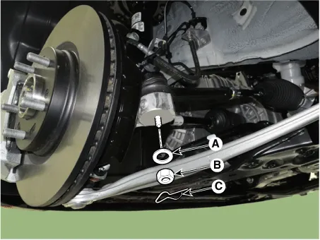
| 3. |
Separate the stabilizer bar link (A) from the strut assembly after loosening the nut.
|

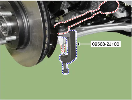
| 4. |
Disconnect the tie rod end ball joint from the knuckle by using the SST (09568-2J100).
|
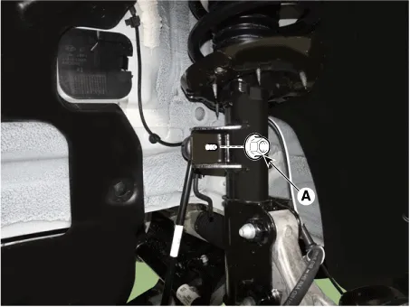
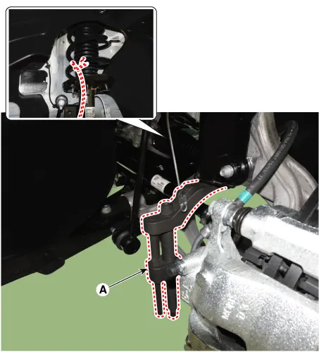
| 5. |
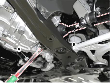
Loosen the lower arm mounting nut (A).
|
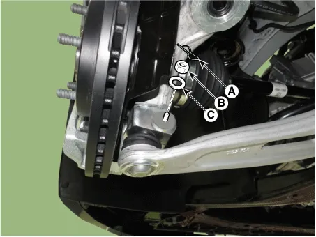
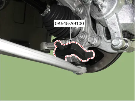
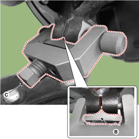
| 6. |
Disconnect lower arm ball joint from the knuckle by using the SST (0K545-A9100).
|
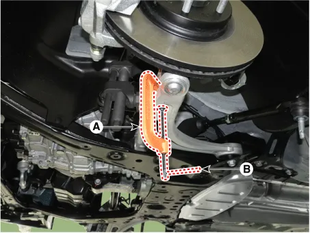
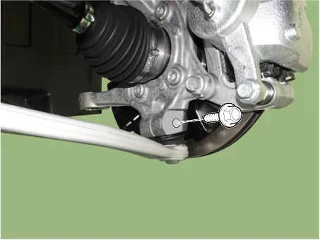
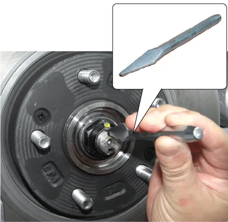
| 7. |
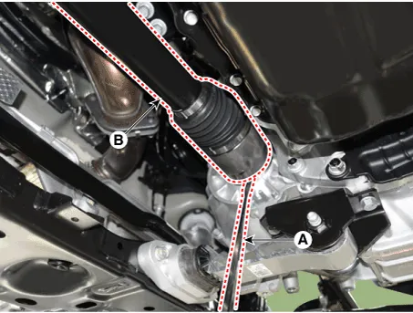
By hammering on a chisel, unlock the driveshaft lock hub nut caulking.
|
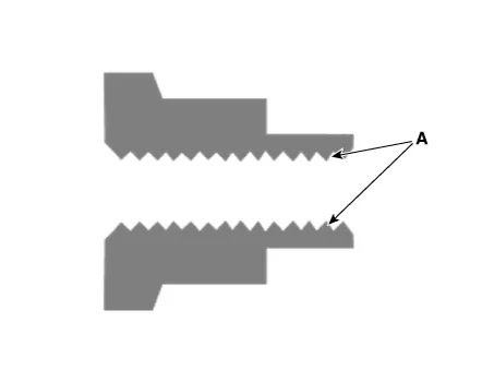
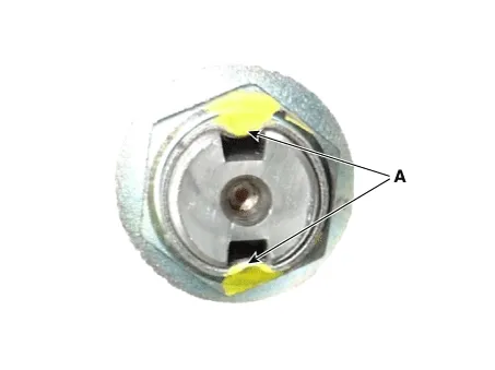
| 8. |
Remove the caulking nut (A) from the front axle.
|

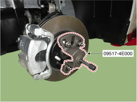
| 9. |
Disconnect the driveshaft from the axle hub by using the SST (09517-4E000).
|
| 10. |
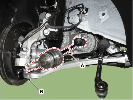
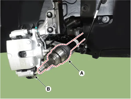
Separate the front driveshaft (A) from the knuckle assembly (B). [LH]
[RH]
|
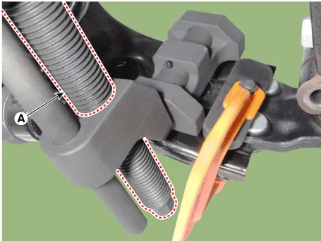
| 11. |
Remove the driveshaft (B) by using the pry bar (A). [LH]
[RH]
|
| Installation |
| 1. |
Install in the reverse order of removal. |
| 2. |
Check the front alignment. (Refer to Suspension System - "Alignment") |
| Inspection |
| 1. |
Check the driveshaft boots for damage and deterioration. |
| 2. |
Check the driveshaft spline for wear or damage. |
| 3. |
Check that there is no water or foreign material in the joint. |
| 4. |
Check the spider assembly for roller rotation, wear or corrosion. |
| 5. |
Check the groove inside the joint case for wear or corrosion. |
| 6. |
Check the dynamic damper for damage or cracks. |
Components and components location Components 1. Wheel side joint assembly 2. Wheel side circlip 3. Wheel side boot band 4.
Other information:
Kia Optima DL3 2019-2026 Service and Repair Manual: License Lamps
Repair procedures Removal 1. Disconnect the negative battery terminal. 2. Remove the lcense lamp (A) by pressing the hook. 3. Disconnect the lcense lamp connector (A).
Kia Optima DL3 2019-2026 Service and Repair Manual: Power Window Motor
Schematic diagrams Circuit Diagram [Safety Window Motor] [Standard Window Motor] Repair procedures Inspection Front Power Window Motor 1. Disconnect the negative battery terminal. 2.
Categories
- Manuals Home
- Kia Optima Owners Manual
- Kia Optima Service Manual
- Identification Numbers
- Steering System
- Body (Interior and Exterior)
- New on site
- Most important about car
