Kia Optima DL3: Lighting System / Mood Lamp Unit
Schematic diagrams
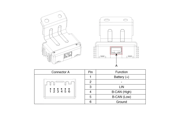
| Connector and Terminal function |
Repair procedures
| Removal |
When removing with a flat-tip screwdriver or remover, wrap protective tape around the tools to prevent damage to components. |

| 1. |
Disconnect the negative battery terminal. |
| 2. |
Remove the crash pad lower panel. (Refer to Body - "Crash Pad Lower Panel") |
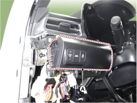
| 3. |
Remove the crash pad garnish [LH]. (Refer to Body - "Crash Pad Garnish") |
| 4. |
Remove the crash pad lower garnish [LH] (A) by loosening the mounting screw.
|
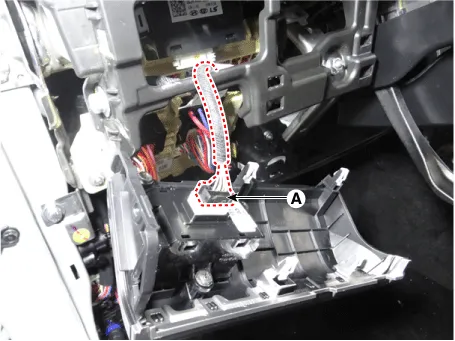
| 5. |
Disconnect the connector (A) from the crash pad lower garnish [LH].
|
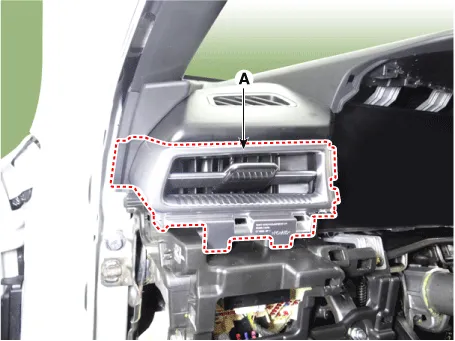
| 6. |
Remove the side air vent (A) by using a flat-tip screwdriver or remover.
|
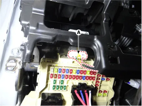
| 7. |
Disconnect the mood lamp unit connector (A).
|
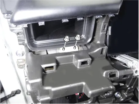
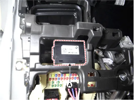
| 8. |
Remove the mood lamp unit (A) by loosening the mounting nuts.
|
| Installation |
| 1. |
Install in the reverse order of removal. |
Repair procedures Removal When removing with a flat-tip screwdriver or remover, wrap protective tape around the tools to prevent damage to components.
Specifications Specifications Items Specifications Rated voltage Front fog lamp switch 5 V Lighting Auto lighting Dimmer & Passing Turn signal lamp Wiper Washer 14.
Other information:
Kia Optima DL3 2019-2026 Service and Repair Manual: Condenser
Components and components location Components Location 1. Condenser Repair procedures Inspection 1. Check the condenser fins for clogging and damage. If clogged, clean them with water, and blow them with compressed air.
Kia Optima DL3 2019-2026 Service and Repair Manual: Heater Control Unit
Components and components location Components Connector Pin Function [Connector A] Pin NO Funtion Pin NO Funtion 1 Ground 11 Ground 2 Clean signal 12 -
Categories
- Manuals Home
- Kia Optima Owners Manual
- Kia Optima Service Manual
- Brake System
- Heating, Ventilation and Air Conditioning
- Battery
- New on site
- Most important about car
