Kia Optima DL3: Body Electrical System / Horn
Specifications
| Specifications |
|
Item |
Specification |
Remark |
|
Operating voltage |
9 - 16 V |
- |
|
Current consumption |
MAX 5.0 A |
At 12 V |
|
Sound level |
111 ± 3 dB |
At 13 V, 2 m |
|
Insulation resistance |
MIN 1 MΩ |
By 500 V megameter |
Components and components location
| Component Location |
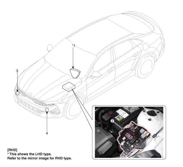
| 1. Horn switch 2. Engine room junction block (Horn fuse) |
3. Horn (Low pitch) 4. Horn (High pitch) |
Repair procedures
| Removal |
| 1. |
Disconnect the negative battery terminal. |
| 2. |
Remove the front bumper assembly. (Refer to Body - "Front Bumper assembly") |
| 3. |
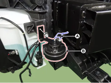
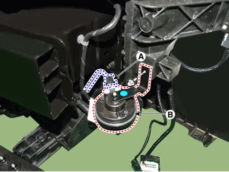
Disconnect the horn connector (A). |
| 4. |
Remove the horn (B) by loosening the bolt.
[Low pitch]
[High pitch]
|
| Installation |
| 1. |
Install in the reverse order of removal. |
| Inspection |
| 1. |
The relay on the horn of this vehicle is implanted into the metal core block PCB of the engine room relay block. |
The semi-conductor type relay inserted in the PCB is impossible to replace. If the relay needs to be replaced, replace the metal core box and conduct a test on it. |

Schematic diagrams Connector and Terminal Function Repair procedures Removal • Use a plastic panel removal tool to remove interior trim pieces without marring the surface.
Repair procedures Removal 1. Disconnect the negative battery terminal. 2. Remove the steering column upper & lower shroud panel.
Other information:
Kia Optima DL3 2019-2026 Service and Repair Manual: Smart Key Diagnostic
Repair procedures Inspection 1. In the body electrical system, failure can be quickly diagnosed by using the vehicle diagnostic system (KDS). The diagnostic system (KDS) provides the following information. (1) Self diagnosis : Checking failure and code number (DTC).
Kia Optima DL3 2019-2026 Service and Repair Manual: Heater & A/C Control Unit (DATC)
Components and components location Components Connector Pin NO Funtion Pin NO Funtion 1 Ground 9 Ground 2 ILL- 10 - 3 - 11
Categories
- Manuals Home
- Kia Optima Owners Manual
- Kia Optima Service Manual
- Motor Driven Power Steering
- Body Electrical System
- Engine Control / Fuel System
- New on site
- Most important about car
