Kia Optima DL3: Body Electrical System / Ignition Switch Assembly
Repair procedures
| Removal |
| 1. |
Disconnect the negative battery terminal. |
| 2. |
Remove the steering column upper & lower shroud panel. (Refer to Body - "Steering Column Shroud Panel") |
| 3. |
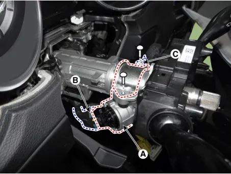
Remove the ignition lock switch assembly (A) by loosening the bolts after disconnecting the connectors (B, C).
|
| Installation |
| 1. |
Install in the reverse order of removal.
|

| Inspection |
| 1. |
Disconnect the ignition switch connector (B) and key warning switch connector (A) from under the steering column.
|
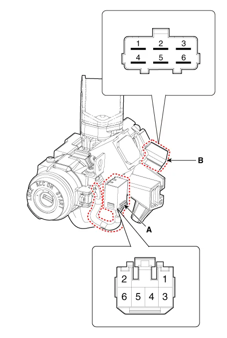
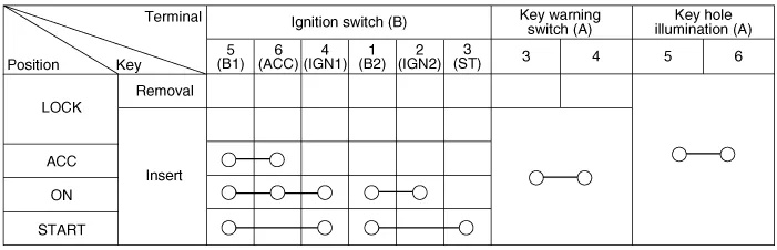
| 2. |
Check for continuity between the terminals.
|
Specifications Specifications Item Specification Remark Operating voltage 9 - 16 V - Current consumption MAX 5.
Other information:
Kia Optima DL3 2019-2026 Service and Repair Manual: Headlamps
Components and components location Component Location 1. Low beam 2. High beam 3. Daytime Running Light / Position lamp 4. Low assist beam 5. Turn signal lamp Schematic diagrams Connector and Terminal Function Connector Terminal Function
Kia Optima DL3 2019-2026 Service and Repair Manual: Compressor oil
Repair procedures Oil Specification 1. The HFC-134a system requires synthetic (PAG) compressor oil whereas the R-12 system requires mineral compressor oil. The two oils must never be mixed. 2. Compressor (PAG) oil varies according to compressor model.
Categories
- Manuals Home
- Kia Optima Owners Manual
- Kia Optima Service Manual
- Cooling System
- Identification Numbers
- Engine Control / Fuel System
- New on site
- Most important about car
