Kia Optima DL3: Installing a Child Restraint System (CRS) / Lower Anchors and Tether for Children (LATCH) System
The LATCH system holds a child restraint during driving and in an accident. This system is designed to make installation of the child restraint easier and reduce the possibility of improperly installing your child restraint. The LATCH system uses anchors in the vehicle and attachments on the child restraint. The LATCH system eliminates the need to use seat belts to secure the child restraint to the rear seats.
Lower anchors are metal bars built into the vehicle. There are two lower anchors for each LATCH seating position that will accommodate a child restraint with lower attachments.
To use the LATCH system in your vehicle, you must have a child restraint with LATCH attachments.
The child seat manufacturer will provide you with instructions on how to use the child seat with its attachments for the LATCH lower anchors.
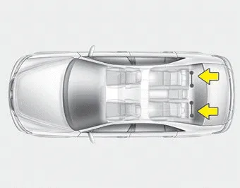
LATCH anchors have been provided in the left and right outboard rear seating positions. Their locations are shown in the illustration. There are no LATCH anchors provided for the center rear seating position.
WARNING - LATCH Lower Anchors
Never attempt to attach a LATCH equipped seat in the center seating position. LATCH lower anchors are only to be used in the left and right rear outboard seating positions.You may damage the anchors or the anchors may fail and break in a collision.
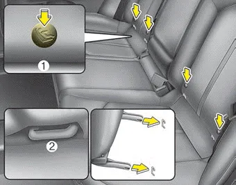
The lower anchor position indicator symbols are located on the left and right rear seat backs to identify the position of the lower anchors in your vehicle (see arrows in illustration).
The LATCH anchors are located between the seatback and the seat cushion of the rear seat left and right outboard seating positions.
❈ (1) : Lower Anchor position indicator
(2) : Lower Anchor
After selecting a proper child seat for your child, check to make sure it fits properly in your vehicle. Follow the instructions provided by the manufacturer when installing the child seat.
To install a LATCH-compatible child restraint in either of the rear outboard seating positions: 1. Move the seat belt buckle away from the lower anchors.
Other information:
Kia Optima DL3 2019-2026 Service and Repair Manual: Hazard Lamp Switch
Schematic diagrams Connector and Terminal Function Repair procedures Removal 1. Disconnect the negative battery terminal. 2. Remove the crash pad garnish [RH]. (Refer to Body - "Crash Pad Garnish") 3.
Kia Optima DL3 2019-2026 Service and Repair Manual: Rear Glass Defogger Switch
Repair procedures Inspection 1. In the body electrical system, failure can be quickly diagnosed by using the vehicle diagnostic system (KDS). The diagnostic system (KDS) provides the following information. (1) Self diagnosis : Checking failure and code number (DTC).
Categories
- Manuals Home
- Kia Optima Owners Manual
- Kia Optima Service Manual
- Cooling System
- Charging System
- Body Electrical System
- New on site
- Most important about car
