Kia Optima DL3: Lighting System / Rheostat
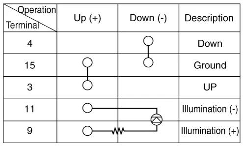
Schematic diagrams
| Connector and Terminal Function |

Repair procedures
| Removal |
| 1. |
Disconnect the negative battery terminal. |
| 2. |
Remove the crash pad lower panel. (Refer to Body - "Crash Pad Lower Panel") |
| 3. |
Remove the crash pad garnish [LH]. (Refer to Body - "Crash Pad Garnish") |
| 4. |
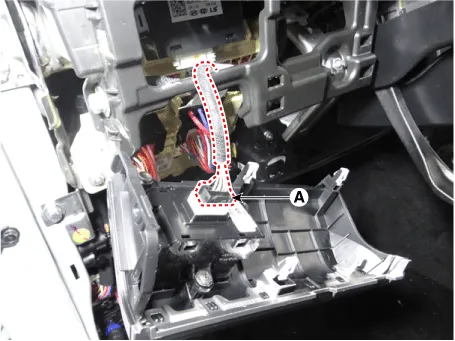
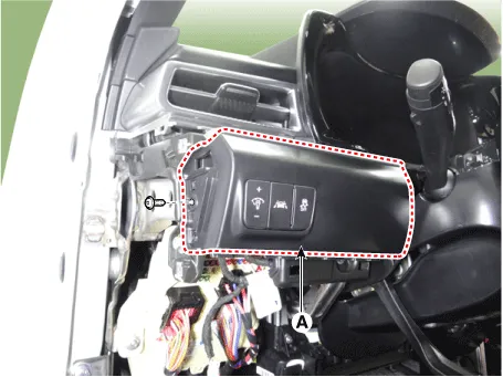
Remove the crash pad lower garnish [LH] (A) by loosening the mounting screw.
|

| 5. |
Disconnect the connector (A) from the crash pad lower garnish [LH].
|
| 6. |
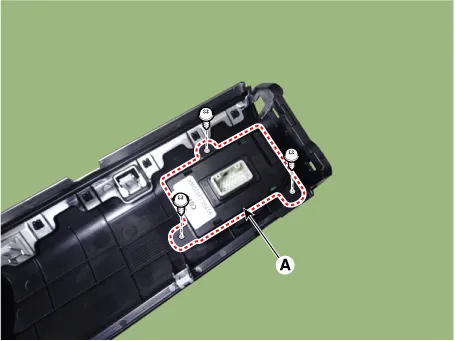
Remove the side crash pad switch (A) by loosening the mounting screws.
|
| Installation |
| 1. |
Install in the reverse order of removal. |
| Inspection |
| 1. |
Disconnect the negative battery terminal. |
| 2. |
Remove the crash pad lower panel. (Refer to Body - "Crash Pad Lower Panel") |
| 3. |
Remove the crash pad garnish [LH]. (Refer to Body - "Crash Pad Garnish") |
| 4. |
Remove the crash pad lower garnish [LH] (A) by loosening the mounting screw.
|
| 5. |
Disconnect the connector (A) from the crash pad lower garnish [LH].
|

| 6. |
Check rheostat switch for continuity.
|
Components and components location Component Location 1. Tail lamp 2. Stop lamp 3. Tail/Stop lamp 4. Back up lamp 5.
Repair procedures Removal When removing with a flat-tip screwdriver or remover, wrap protective tape around the tools to prevent damage to components.
Other information:
Kia Optima DL3 2019-2026 Service and Repair Manual: Relaxion Comfort Seat
Components and components location Component Location 1. Relaxion comfort switch 2. Walk-in switch 3. Relaxion comfort seat unit (RCSU) Schematic diagrams Connector and Terminal Function Pin Function Connector A Co
Kia Optima DL3 2019-2026 Service and Repair Manual: Receiver-Drier
Repair procedures Replacement 1. Remove the condenser. 2. Remove the cap (A) on the bottom of the condenser with a L wrench. Tightening torque : 9.81 - 14.71 N.
Categories
- Manuals Home
- Kia Optima Owners Manual
- Kia Optima Service Manual
- Body (Interior and Exterior)
- Battery
- Floor Console Assembly
- New on site
- Most important about car
