Kia Optima DL3: Motor Driven Power Steering / MDPS Column and Housing
Repair procedures
| Removal |
| 1. |
Align the steering wheel so that the front wheels to facing straight ahead.
|

| 2. |
Turn the ignition OFF and disconnect the negative (-) battery terminal. |
| 3. |
Remove the multifunction switch module. (Refer to Body Electrical System - "Multifunction Switch") |
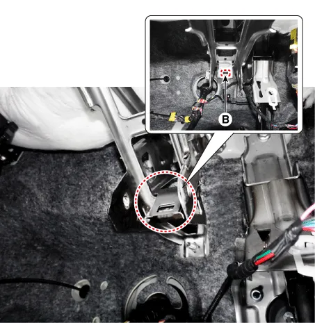
| 4. |
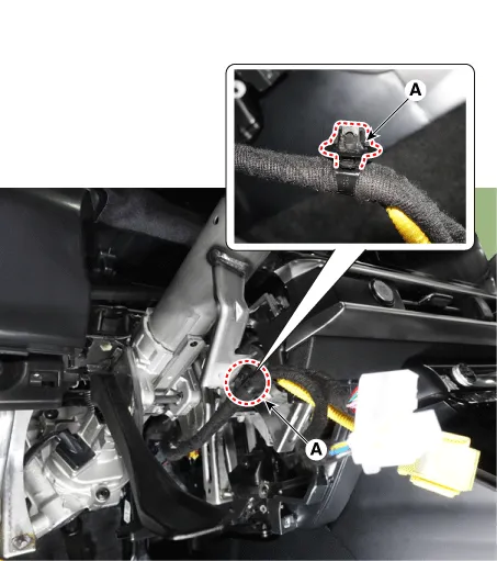
Remove the wiring fix clip (A) from the steering column.
|
| 5. |
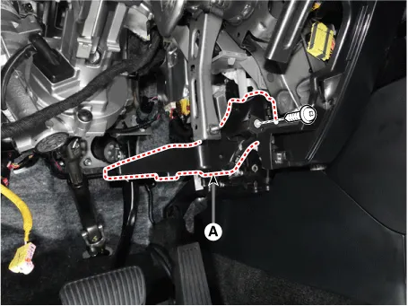
Remove the driver shower duct (A) after loosening the mounting screw.
|
| 6. |
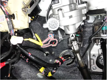
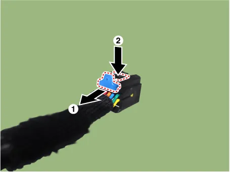
Disconnect the MDPS power pack connectors (A).
|


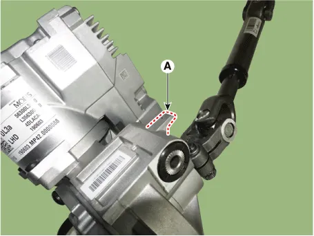
| 7. |
Loosen the bolt (A) and remove the universal joint (B).
|

| 8. |
Remove the stop lamp switch. (Refer to Brake System - "Stop Lamp Switch") |
| 9. |
Remove the MDPS Column & Housing (A) after loosening the mounting bolt and nuts.
|

| Disassembly |
| 1. |
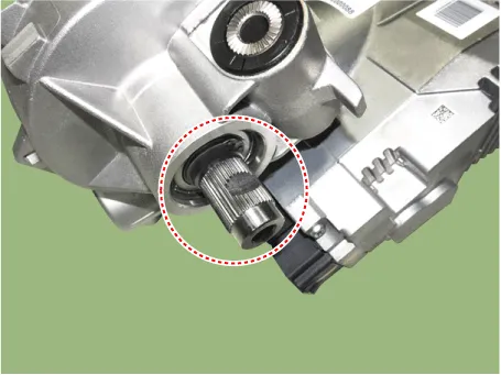
Remove the steering universal joint assembly (A) after loosening the mounting bolt.
|
| Assembly |
|
| 1. |
Assemble in the reverse order of disassembly. |
| Inspection |
| 1. |
Check the steering column for damage and deformation. |
| 2. |
Check the joint bearing for damage and wear. |
| 3. |
Check the tilt bracket for damage and cracks. |
| 4. |
Check the key lock assembly for proper operation and replace it if necessary. |
| Installation |
|
| 1. |
Install in the reverse order of removal. |
| 2. |
Perform the "EPS Type Recognition" by KDS. (Refer to MDPS System - "Diagnosis with KDS") |
| 3. |
Perform the "SAS Calibration" by KDS. (Refer to MDPS System - "Diagnosis with KDS") |
Repair procedures Inspection 1. MDPS power pack assembly failure can be quickly diagnosed using the vehicle diagnostic system (KDS).
Components and components location Components 1. Steering gear box 2. STie rod end 3. Dust cap Repair procedures Removal 1.
Other information:
Kia Optima DL3 2019-2026 Service and Repair Manual: Receiver-Drier
Repair procedures Replacement 1. Remove the condenser. 2. Remove the cap (A) on the bottom of the condenser with a L wrench. Tightening torque : 9.81 - 14.71 N.
Kia Optima DL3 2019-2026 Service and Repair Manual: Intake Actuator
Components and components location Components Location 1. Intake actuator Description and operation Description The intake actuator is located at the blower unit. It regulates the intake door by a signal from the control unit.
Categories
- Manuals Home
- Kia Optima Owners Manual
- Kia Optima Service Manual
- Engine Mechanical System
- Cooling System
- Steering System
- New on site
- Most important about car
