Kia Optima DL3: Manual heating and air conditioning / Mode selection
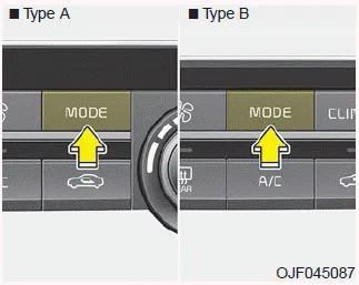
The mode selection button controls the direction of the air flow through the ventilation system.
The air flow outlet port is converted as follows:

Refer to the illustration in the “Manual climate control system”.
Face-Level

Air flow is directed toward the upper body and face. Additionally, each outlet can be controlled to direct the air discharged from the outlet.
Bi-Level

Air flow is directed towards the face and the floor.
Floor-Level

Most of the air flow is directed to the floor, with a small amount of the air being directed to the windshield and side window defrosters.
Floor/Defrost-Level

Most of the air flow is directed to the floor and the windshield with a small amount directed to the side window defrosters.
Defrost-Level
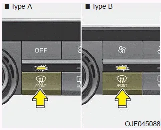
Most of the air flow is directed to the windshield with a small amount of air directed to the side window defrosters.
Instrument panel vents
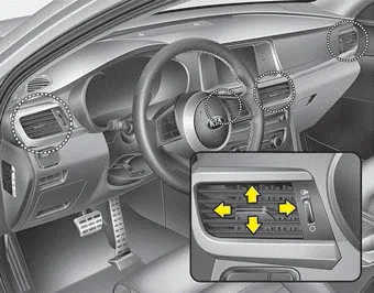
The outlet vents can be opened or closed separately using the thumbwheel (if equipped).
Also, you can adjust the direction of air delivery from these vents using the vent control lever as shown.
The heating and cooling system can be controlled manually by pressing buttons or turning knob(s) other than the AUTO button. In this case, the system works sequentially according to the order of buttons or knob(s) selected.
The temperature will increase to the maximum (HI) by turning the knob to the extreme right. The temperature will decrease to the minimum (Lo) by turning the knob to the extreme left.
Other information:
Kia Optima DL3 2019-2026 Service and Repair Manual: Heating, Ventilation and Air Conditioning
Service data Service Data Air Conditioner ltem Specification Compressor Type 6SAS14 Oil type & Capacity ND-OIL 12 80 ± 10 cc (2.82 ± 0.
Kia Optima DL3 2019-2026 Service and Repair Manual: Receiver-Drier
Repair procedures Replacement 1. Remove the condenser. 2. Remove the cap (A) on the bottom of the condenser with a L wrench. Tightening torque : 9.81 - 14.71 N.
Categories
- Manuals Home
- Kia Optima Owners Manual
- Kia Optima Service Manual
- Heating, Ventilation and Air Conditioning
- Automatic Transaxle System
- Rear Brake Disc
- New on site
- Most important about car
