
Kia Optima DL3: Lubrication System / Oil Pressure Switch
Repair procedures
| Removal and Installation |
| 1. |
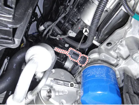
Disconnect the oil pressure switch connector (A) and then remove the oil pressure switch (B).
|
| 2. |
Install in the reverse order of removal.
|

| Inspection |
| 1. |
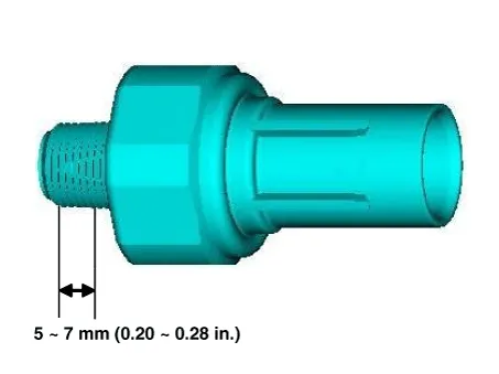
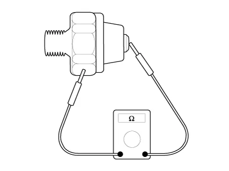
Check the continuity between the terminal and the body with an ohmmeter. If there is no continuity, replace the oil pressure switch.
|
| 2. |
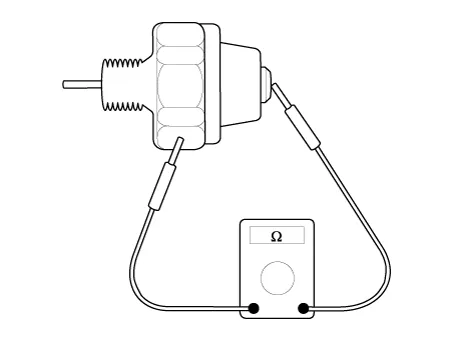
Check the continuity between the terminal and the body when the fine wire is pushed. If there is continuity even when the fine wire is pushed, replace the switch. |
| 3. |
If there is no continuity when a 50 kPa (0.50 kgf/cm², 7.25 psi) is applied through the oil hole, the switch is operating properly. Check for air leakage. If air leaks, the diaphragm is broken. Replace it.
|
Components and components location Components 1. Oil screen gasket 2. Oil screen 3. Oil pan Repair procedures Removal 1.
Repair procedures Removal and Installation 1. Remove the oil level gauge (A). 2. Install in the reverse order of removal.
Other information:
Kia Optima DL3 2019-2026 Service and Repair Manual: Blower Unit
Components and components location Component Location 1. Blower unit assembly Components 1. Intake actuator 2. Cluster ionizer 3. Air filter 4. Blower motor assembly 5.
Kia Optima DL3 2019-2026 Service and Repair Manual: Heater & A/C Control Unit (Manual)
Components and components location Components Connector Pin Function [Connector A] Pin NO Funtion Pin NO Funtion 1 Battery (+) 21 IGN2 2 ILL+ (TAIL) 22 IGN1
Categories
- Manuals Home
- Kia Optima Owners Manual
- Kia Optima Service Manual
- Headlamps
- Cooling System
- Timing Chain
- New on site
- Most important about car
