Kia Optima DL3: Parking Distance Warning (PDW) / Parking Distance Warning (PDW) Sensor
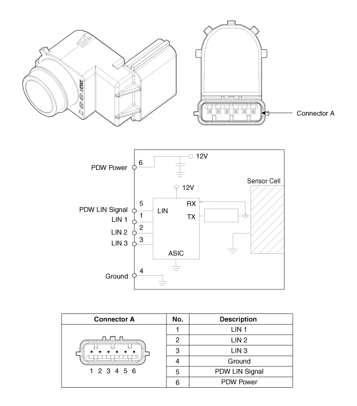
Schematic diagrams
| Circuit Diagram |
Repair procedures
| Removal |
Parking Distance Warning-Forward (PDW-F) Sensor
| 1. |
Remove the front bumper assembly. (Refer to Body - "Front Bumper Assembly") |
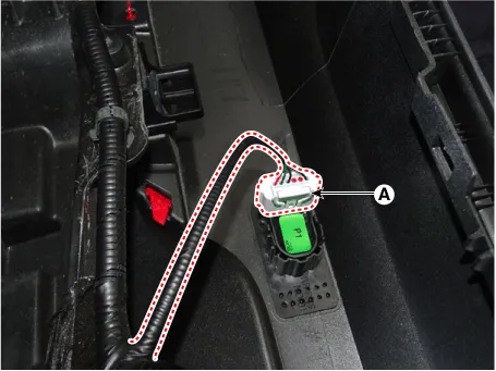
| 2. |
Disconnect the connector (A) from the PDW-F sensor.
|

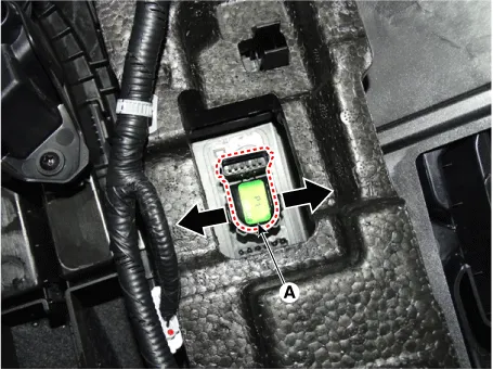
| 3. |
Remove the PDW-F sensor (A) by pushing the sensor holder in the direction of arrow.
|
Parking Distance Warning-Reverse (PDW-R) Sensor
| 1. |
Remove the rear bumper assembly. (Refer to Body - "Rear Bumper Assembly") |
| 2. |
Disconnect the connector (A) from the PDW-R sensor.
|
| 3. |
Remove the PDW-R sensor (A) by pushing the sensor holder in the direction of arrow.
|

| Installation |
| 1. |
Install in the reverse order of removal. |
Specifications Specifications Item Specification Ultrasonic sensor Voltage rating DC 12 V Detecting range 30 - 120 cm (11.
Schematic diagrams Connector and Terminal Function Pin Function Pin Function 1 PAS mode switch 13 SVM mode indicator 2 PAS mode indicator 14 SVM mode switch 3 - 15 - 4 Detent 16 Ground 5 EPB switch1 17 EPB switch2 6 EPB switch3 18 EPB switch4 7 - 19 - 8 - 20 IGN1 9 Battery (+) 21 illumination (+) 10 - 22 - 11 ISG mode indicator 23 illumination (-) 12 ISG mode switch 24 Auto hold mode Repair procedures Inspection 1.
Other information:
Kia Optima DL3 2019-2026 Service and Repair Manual: Power Door Lock Switch
Repair procedures Inspection Power Window Main Switch Diagnosis With KDS 1. In the body electrical system, failure can be quickly diagnosed by using the vehicle diagnostic system (KDS). The diagnostic system (KDS) provides the following information.
Kia Optima DL3 2019-2026 Service and Repair Manual: Power Window Motor
Schematic diagrams Circuit Diagram [Safety Window Motor] [Standard Window Motor] Repair procedures Inspection Front Power Window Motor 1. Disconnect the negative battery terminal. 2.
Categories
- Manuals Home
- Kia Optima Owners Manual
- Kia Optima Service Manual
- Suspension System
- Identification Numbers
- Charging System
- New on site
- Most important about car
