Kia Optima DL3: Power Windows / Power Window Motor
Schematic diagrams
| Circuit Diagram |
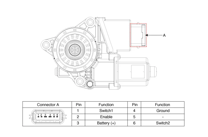
[Safety Window Motor]
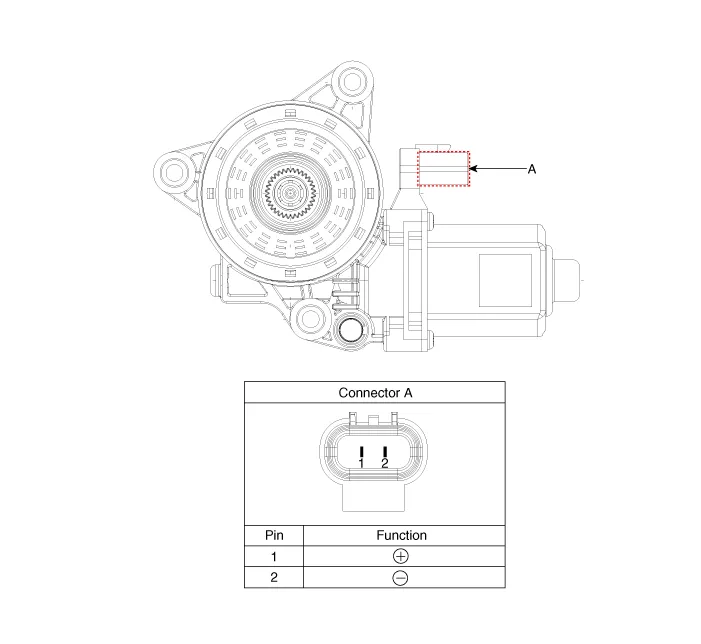
[Standard Window Motor]
Repair procedures
| Inspection |
Front Power Window Motor
| 1. |
Disconnect the negative battery terminal. |
| 2. |
Remove the front door trim. (Refer to Body - "Front Door Trim") |
| 3. |
Disconnect the connector from the motor.
|
| 4. |
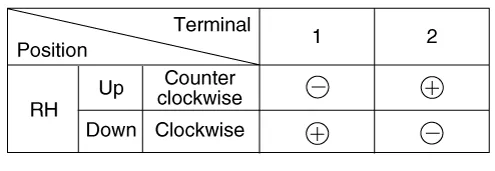
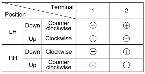
Connect the motor terminals directly to battery voltage (12V) and check that the motor operates smoothly. Next, reverse the polarity and check that the motor operates smoothly in the reverse direction. If the operation is abnormal, replace the motor. [Safety window motor]
[Standard window motor]
|
Rear Power Window Motor
| 1. |
Disconnect the negative battery terminal. |
| 2. |
Remove the rear door trim. (Refer to Body - "Rear Door Trim") |
| 3. |
Disconnect the connector from the motor.
|
| 4. |
Connect the motor terminals directly to battery voltage (12V) and check that the motor operates smoothly. Next, reverse the polarity and check that the motor operates smoothly in the reverse direction. If the operation is abnormal, replace the motor. [Safety window motor]
[Standard window motor]
|
| Removal |
Front Power Window Motor
| 1. |
Disconnect the negative battery terminal. |
| 2. |
Remove the front door trim. (Refer to Body - "Front Door Trim") |
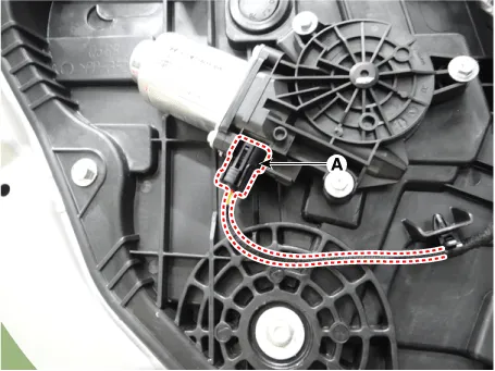
| 3. |
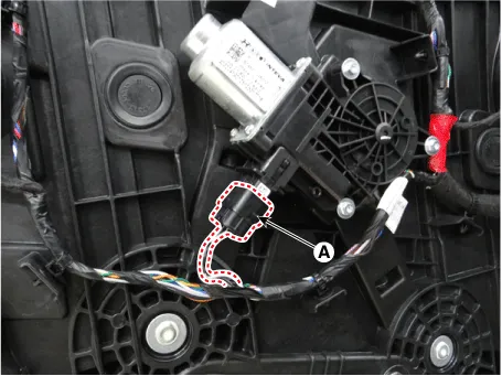
Disconnect the front power window motor connector (A).
|
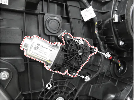
| 4. |
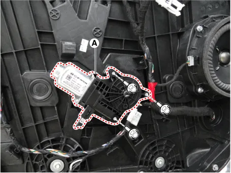
Remove the front power window motor (A) after loosening the mounting bolts.
|
Rear Power Window Motor
| 1. |
Disconnect the negative battery terminal. |
| 2. |
Remove the rear door trim. (Refer to Body - "Rear Door Trim") |
| 3. |
Disconnect the rear power window motor connector (A).
|
| 4. |
Remove the rear power window motor (A) after loosening the mounting bolts.
|
| Installation |
| 1. |
Install in the reverse order of removal. |
Components and components location Component Location 1. Power window main switch 2. Rear window main switch 3.
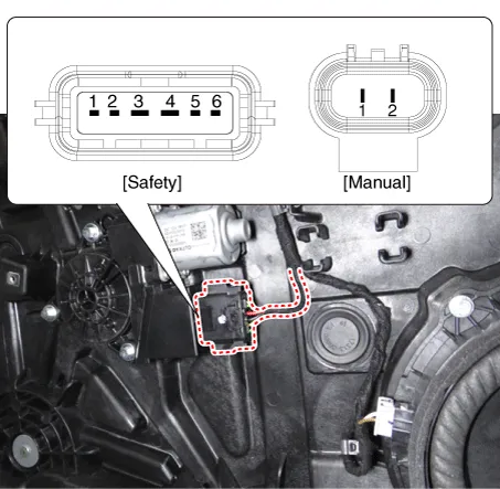
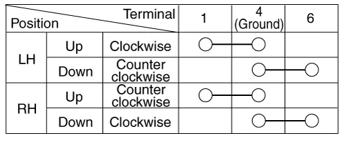
Schematic diagrams Connector and Terminal Function Power Window Main Switch Pin Function 1 B-CAN (Low) 2 B-CAN (High) 3 Ground (Assist safety) 4 Assist safety 5 LIN (For IMS) 6 Battery (+) 7 IGN1 8 Driver safety 9 IMS Switch (For IMS) / Mirror Common (For Non IMS) 10 Mirror unfolding motor (Non IMS) 11 Mirror folding motor (Non IMS) 12 Mirror horizontal LH (Non IMS) 13 Mirror vertical LH (Non IMS) 14 Mirror vertical RH (Non IMS) 15 Mirror horizontal RH (Non IMS) 16 Ground Power Window Sub Switch Pin Function Safety Type Manual Type 1 Ground (Illumination -) Ground 2 Door lock switch Door lock switch 3 Door unlock switch Window down motor 4 Battery + (Illumination +) Door unlock switch 5 Ground Window up motor 6 Door lock indicator Door lock indicator 7 Safety power window Driver window down 8 - Window enble 9 Ground (Illumination -) 10 Driver window up 11 Ground (Illumination +) 12 Battery (+) Power Window Rear Switch [Seat Warmer Type] Pin Function Safety Type Manual Type 1 Ground (Illumination -) Ground 2 Seat warmer (High) Seat warmer (High) 3 Seat warmer (Low) Window down motor 4 Battery + (Illumination +) Seat warmer (Low) 5 Ground Window up motor 6 - Seat warmer switch 7 Safety power window Driver window down 8 Seat warmer switch Window enble 9 Ground (Illumination -) 10 Driver window up 11 Battery + (Illumination +) 12 Battery (+) [Non-Seat Warmer Type] Pin Function Safety Type Manual Type 1 Ground (Illumination -) Ground 2 - - 3 - Window down motor 4 Battery + (Illumination +) - 5 Ground Window up motor 6 - - 7 Safety power window Driver window down 8 - Window enble 9 Ground (Illumination -) 10 Driver window up 11 Battery + (Illumination +) 12 Battery (+) Repair procedures Inspection Diagnosis With KDS 1.
Other information:
Kia Optima DL3 2019-2026 Service and Repair Manual: Hazard Lamp Switch
Schematic diagrams Connector and Terminal Function Repair procedures Removal 1. Disconnect the negative battery terminal. 2. Remove the crash pad garnish [RH]. (Refer to Body - "Crash Pad Garnish") 3.
Kia Optima DL3 2019-2026 Service and Repair Manual: Power Door Mirror Switch
Schematic diagrams Connector and Terminal Function Pin Function 1 B-CAN (Low) 2 B-CAN (High) 3 Ground (Assist safety) 4 Assist safety 5 LIN (For IMS)
Categories
- Manuals Home
- Kia Optima Owners Manual
- Kia Optima Service Manual
- Floor Console Assembly
- Heating, Ventilation and Air Conditioning
- Brake System
- New on site
- Most important about car
