Kia Optima DL3: Advanced Driver Assistance System (ADAS) / Parking Distance Warning (PDW)
Specifications
| Specifications |
|
Item |
Specification |
|
|
Ultrasonic sensor |
Voltage rating |
DC 12 V |
|
Detecting range |
30 - 120 cm (11.8 - 47.2 in.) |
|
|
Operation voltage |
DC 9 - 16 V |
|
|
Operation current |
MAX. 350mA |
|
|
Operation frequency |
48 ± 5 KHz |
|
|
Number of sensors |
8 units |
|
Components and components location
| Component Location |
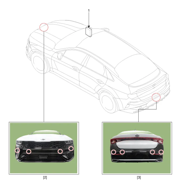
| 1. Integrated body control unit
(IBU) 2. Parking distance warning-forward (PDW-F) sensor |
3. Parking distance warning-reverse
(PDW-R) sensor |
Description and operation
| Description |
| • |
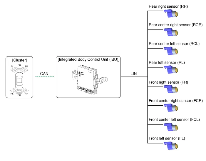
PDW consists of 8 sensors (front : 4 units, rear : 4 units) that are used to detect obstacles and transmit the result in three separate warning levels, the first, second and third to IBU via LIN communication. |
| • |
IBU decides the alarm level by the transmitted communication message from the slave sensors, then operates the buzzer or transmits the data for display. |
Block Diagram
System Operation Specification
| Initial mode |
| 1. |
System initializing time
|
| 2. |
PDW recognizes LID and sets the sensor ID up during initialization. |
| 3. |
PDW activates each sensor and then executes the diagnosis after finishing initialization of IPM(IBU). |
| 4. |
PDW starting buzzer is normally worked, when sensor does not send an error message and after finishing error diagnosis. |
| 5. |
If any failure is received from the any sensors, PDW starting buzzer does not work but the failure alarm is operated for a moment. If you have display option, warning sign is also displayed.
|

| 6. |
IBU memorizes the completed initializing status of sensor. |
| Normal mode |
| 1. |
PDW-F : Lin communication starts and keeps the routine after IGN1 ON+D gear + below 15 km/h. PDW-R : Lin communication starts and keeps the routine after IGN1 ON+R gear |
| 2. |
After initializing, the routine starts at once without PDW starting warning sound. |
| 3. |
The obstacle alarm has 3 levels in 1, 2 and 3 step levels; alarms 1 and 2 have intermittent audible sounds, while alarm 3 has continuous audible sound. For the front ultrasonic sensor level 1 alarm does not exist. |
| 4. |
In display, the data of each sensor is sent from IBU to display, for example cluster. |
| 5. |
The efficient vehicle speed of PDW operation is under 10Km/h. |
| 6. |
Operation doesn't start or stop in N or P gears. |
Schematic diagrams Connector and Terminal Function Pin Function Pin Function 1 PAS mode switch 13 SVM mode indicator 2 PAS mode indicator 14 SVM mode switch 3 - 15 - 4 Detent 16 Ground 5 EPB switch1 17 EPB switch2 6 EPB switch3 18 EPB switch4 7 - 19 - 8 - 20 IGN1 9 Battery (+) 21 illumination (+) 10 - 22 - 11 ISG mode indicator 23 illumination (-) 12 ISG mode switch 24 Auto hold mode Repair procedures Removal • When prying with a flat-tip screwdriver or using a prying trim tool, wrap protective tap around the tool and related parts to prevent damage.
Schematic diagrams Circuit Diagram Repair procedures Removal Parking Distance Warning-Forward (PDW-F) Sensor 1.
Other information:
Kia Optima DL3 2019-2026 Service and Repair Manual: Integrated Memory Seat (IMS) Switch
Schematic diagrams Connector and Terminal Function Repair procedures Removal When prying with a flat-tip screwdriver or use a prying trim tool, wrap it with protective tape, and apply protective tape around the related parts, to prevent dam
Kia Optima DL3 2019-2026 Service and Repair Manual: Evaporator Temperature Sensor
Description and operation Description The evaporator temperature sensor will detect the evaporator core temperature and interrupt compressor relay power in order to prevent evaporator from freezing by excessive cooling. The evaporator temperature sensor has the Negative Temperature Coefficient (NTC).
Categories
- Manuals Home
- Kia Optima Owners Manual
- Kia Optima Service Manual
- Suspension System
- Headlamps
- Brake System
- New on site
- Most important about car
