Kia Optima DL3: Parking Distance Warning (PDW) / Parking Distance Warning (PDW) ON/OFF Switch
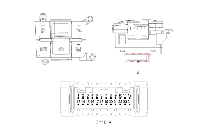
Schematic diagrams
| Connector and Terminal Function |
|
Pin |
Function |
Pin |
Function |
|
1 |
PAS mode switch |
13 |
SVM mode indicator |
|
2 |
PAS mode indicator |
14 |
SVM mode switch |
|
3 |
- |
15 |
- |
|
4 |
Detent |
16 |
Ground |
|
5 |
EPB switch1 |
17 |
EPB switch2 |
|
6 |
EPB switch3 |
18 |
EPB switch4 |
|
7 |
- |
19 |
- |
|
8 |
- |
20 |
IGN1 |
|
9 |
Battery (+) |
21 |
illumination (+) |
|
10 |
- |
22 |
- |
|
11 |
ISG mode indicator |
23 |
illumination (-) |
|
12 |
ISG mode switch |
24 |
Auto hold mode |
Repair procedures
| Inspection |
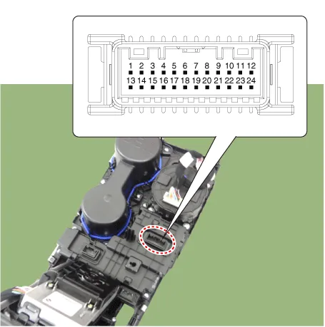
| 1. |
Remove the side crash pad switch. |
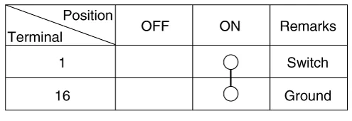
| 2. |
Operate the PDW on/off switch, then check for continuity between terminals.
|
| Removal |
|

| 1. |
Disconnect the negative battery terminal. |
| 2. |
Remove the console upper cover. (Refer to Body - "Floor Console Assembly") |
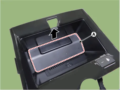
| 3. |
Remove the wireless power charger pad (A).
|
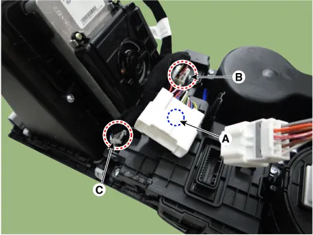
| 4. |
Disconnect the main connector fastener (A), consol switch connector (B) and wireless power charger indicator connector (C).
|
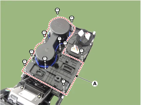
| 5. |
Remove the cup holder assembly (A) after loosening the mounting screws.
|
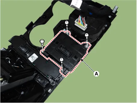
| 6. |
Remove the console switch (A) after loosening the mounting screws.
|
| Installation |
| 1. |
Install in the reverse order of removal. |
Schematic diagrams Circuit Diagram Repair procedures Removal Parking Distance Warning-Forward (PDW-F) Sensor 1.
Components and components location Component Location 1. Cluster (USM) 2. Parking collision-avoidance assist (PCA) Unit 3.
Other information:
Kia Optima DL3 2019-2026 Service and Repair Manual: Ventilated and Heated Seat Switch
Schematic diagrams Connector and Terminal Function [Front Seat] [Ventilation+Heater Type / Non-Heater Type] Pin Function Pin Function Ventilation+Heater Type Non-Heater Type Ventilation+Heater Type Non-Heater Type
Kia Optima DL3 2019-2026 Service and Repair Manual: Power Mosfet
Description and operation Description It is installed to the DATC and adjusts the fan rpm by precisely controlling the voltage applied to the blower motor. Repair procedures Inspection 1. Turn the ignition switch ON.
Categories
- Manuals Home
- Kia Optima Owners Manual
- Kia Optima Service Manual
- Identification Numbers
- Motor Driven Power Steering
- Floor Console Assembly
- New on site
- Most important about car
