Kia Optima DL3: Lighting System / Vanity Lamp
Repair procedures
| Removal |
When removing with a flat-tip screwdriver or remover, wrap protective tape around the tools to prevent damage to components. |

| 1. |
Disconnect the negative battery terminal. |
| 2. |
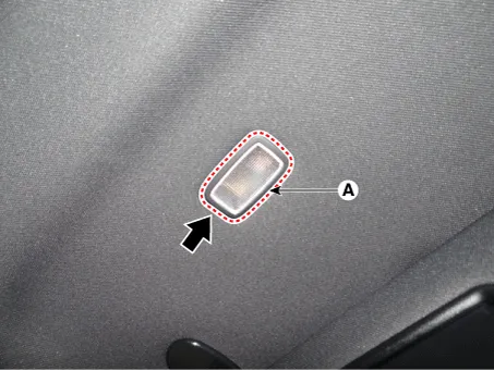
Remove the vanity lamp (A) by using a flat-tip screwdriver or remover.
|
| 3. |
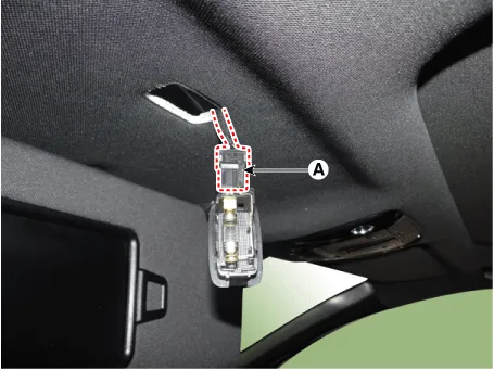
Disconnect the connector (A) from the vanity lamp.
|
| Installation |
| 1. |
Install in the reverse order of removal. |
| Replacement |
When removing with a flat-tip screwdriver or remover, wrap protective tape around the tools to prevent damage to components. |
| 1. |
Disconnect the negative battery terminal. |
| 2. |
Remove the vanity lamp (A) by using a flat-tip screwdriver or remover.
|
| 3. |
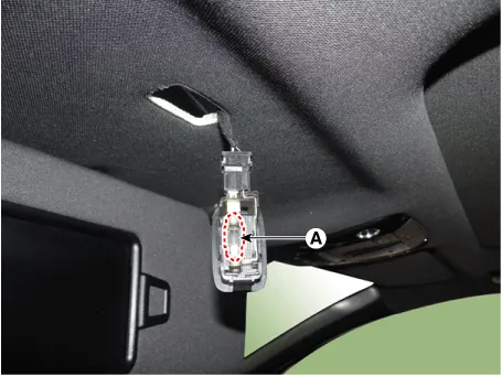
Replace the vanity lamp bulb (A).
|
Repair procedures Removal When removing with a flat-tip screwdriver or remover, wrap protective tape around the tools to prevent damage to components.
Repair procedures Removal When removing with a flat-tip screwdriver or remover, wrap protective tape around the tools to prevent damage to components.
Other information:
Kia Optima DL3 2019-2026 Service and Repair Manual: Multifunction Switch
Specifications Specifications Items Specifications Rated voltage Front fog lamp switch 5 V Lighting Auto lighting Dimmer & Passing Turn signal lamp Wiper Was
Kia Optima DL3 2019-2026 Service and Repair Manual: Evaporator Temperature Sensor
Description and operation Description The evaporator temperature sensor will detect the evaporator core temperature and interrupt compressor relay power in order to prevent evaporator from freezing by excessive cooling. The evaporator temperature sensor has the Negative Temperature Coefficient (NTC).
Categories
- Manuals Home
- Kia Optima Owners Manual
- Kia Optima Service Manual
- Battery
- Lift And Support Points
- Rear Brake Disc
- New on site
- Most important about car
