Kia Optima DL3: Rear Suspension System / Rear Lower Arm
Repair procedures
| Removal |
| 1. |
Disconnect the (-) battery terminal. |
| 2. |
Remove the rear wheel and tire. (Refer to Tires/Wheels - "Wheel") |
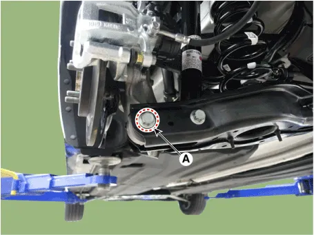
| 3. |
Loosen the bolt and nut (A) and then remove the rear lower arm from the rear axle.
|

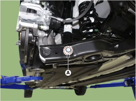
| 4. |
Loosen the bolt and nut (A) and remove the rear shock absorber from the rear lower arm.
|
| 5. |
Loosen the bolt and nut (A) and then disconnect the rear stabilizer link from the rear lower arm.
|
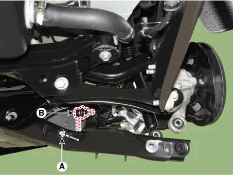
| 6. |
Remove the rear coil spring (A).
|
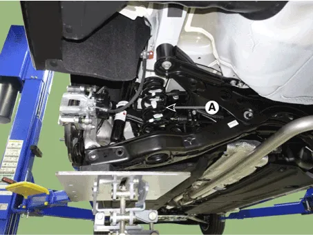
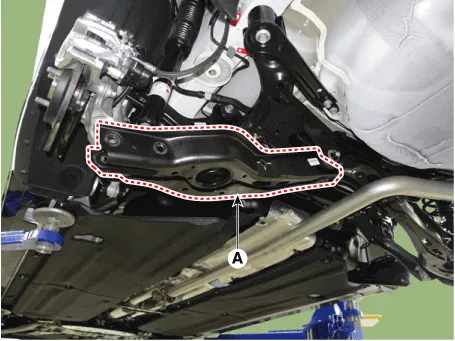
| 7. |
Loosen the bolt and nut and then remove the rear lower arm (A).
|
| Inspection |
| 1. |
Check the bushing for wear and deterioration. |
| 2. |
Check the rear lower arm for deformation. |
| 3. |
Check the coil spring and spring pad for deterioration and deformation. |
| 4. |
Check for all bolts and nut. |
| Installation |
| 1. |
Install in the reverse order of removal. |
| 2. |
Check the alignment. (Refer to Suspension System - "Alingment") |
Repair procedures Removal 1. Disconnect the (-) battery terminal. 2. Remove the rear wheel and tire.
Repair procedures Removal 1. Disconnect the (-) battery terminal. 2. Remove the rear wheel and tire.
Other information:
Kia Optima DL3 2019-2026 Service and Repair Manual: Power Door Mirror Actuator
Schematic diagrams Connector and Terminal Function Repair procedures Inspection 1. Disconnect the negative battery terminal. 2. Remove the front door trim. (Refer to Body - "Front Door Trim") 3.
Kia Optima DL3 2019-2026 Service and Repair Manual: Rear Glass Defogger Switch
Repair procedures Inspection 1. In the body electrical system, failure can be quickly diagnosed by using the vehicle diagnostic system (KDS). The diagnostic system (KDS) provides the following information. (1) Self diagnosis : Checking failure and code number (DTC).
Categories
- Manuals Home
- Kia Optima Owners Manual
- Kia Optima Service Manual
- Engine Control / Fuel System
- Motor Driven Power Steering
- Charging System
- New on site
- Most important about car
