Kia Optima DL3: Suspension System / Rear Suspension System
Components and components location
| Components and Components Location |
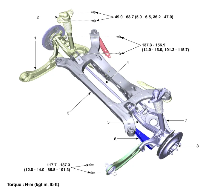
| 1. Trailing arm 2. Rear shock absorber 3. Rear suspension 4. Rear stabilizer bar |
5. Rear upper arm 6. Rear assist arm 7. Rear lower arm 8. Rear axle assembly |
- Rear Shock Absorber
- Rear Coil Spring
- Rear Upper Arm
- Rear Lower Arm
- Rear Assist Armature
- Trailing Arm
- Rear Stabilizer Bar
- Rear sub frame
Repair procedures Removal 1. Disconnect the (-) battery terminal. 2. Loosen the bolt (A) and remove the universal joint (B).
Components and components location Components Repair procedures Removal 1. Disconnect the (-) battery terminal.
Other information:
Kia Optima DL3 2019-2026 Service and Repair Manual: Blower Motor
Repair procedures Inspection 1. Connect the battery voltage and check the blower motor rotation. 2. If the blower motor does not operate well, substitute with a known-good blower motor and check for proper operation.
Kia Optima DL3 2019-2026 Service and Repair Manual: Heater & A/C Control Unit (DATC)
Components and components location Components Connector Pin NO Funtion Pin NO Funtion 1 Ground 9 Ground 2 ILL- 10 - 3 - 11
Categories
- Manuals Home
- Kia Optima Owners Manual
- Kia Optima Service Manual
- Suspension System
- Restraint
- Body Electrical System
- New on site
- Most important about car
