Kia Optima DL3: Rear Suspension System / Rear sub frame
Repair procedures
| Removal |
| 1. |
Disconnect the (-) battery terminal. |
| 2. |
Remove the rear wheel and tire. (Refer to Tires/Wheels - "Wheel") |
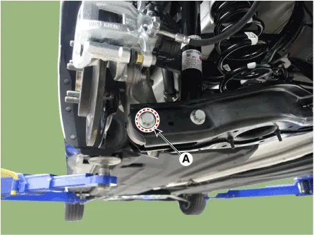
| 3. |
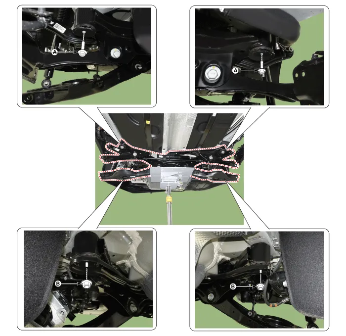
Remove the under cover (A).
|

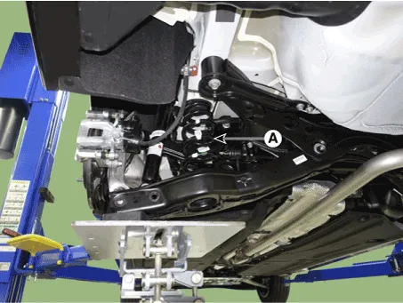
| 4. |
Loosen the bolt and nut (A) and then remove the rear lower arm from the rear axle.
|

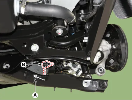
| 5. |
Loosen the bolt and nut (A) and remove the rear shock absorber from the rear lower arm.
|
| 6. |
Loosen the bolt and nut (A) and then disconnect the rear stabilizer link from the rear lower arm.
|
| 7. |
Remove the rear coil spring (A).
|
| 8. |
Remove the rear axle assembly. (Refer to Driveshaft and axle - "Rear Hub - Carrier") |
| 9. |
Remove the rear muffler. G 2.0 NU MPI (Refer to Engine Mechanical System - "Muffler") G 2.5 GDI THETA II (Refer to Engine Mechanical System - "Muffler") |
| 10. |
Support the jack and loosen the subframe bolts and nuts.
|
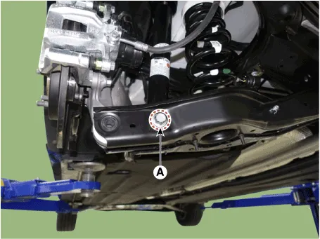
| 11. |
Loosen the bolts and then remove the rear sub frame stay (A).
|
| 12. |
Slowly lower the jack to remove the rear sub frame.
|

| 13. |
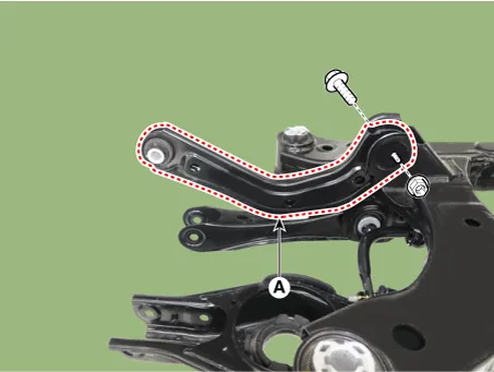
Loosen the bolt and nut and remove the rear upper arm (A) from the rear sub frame.
|
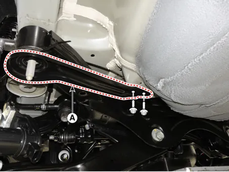
| 14. |
Loosen the bolt and nut and remove the rear assist arm (A) from the rear sub frame.
|
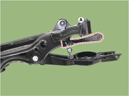
| 15. |
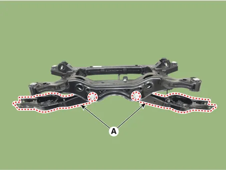
Loosen the bolts and nuts and remove the rear lower arm (A) from the rear sub frame.
|
| 16. |
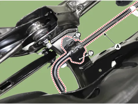
Loosen the stabilizer bracket bolts and remove the rear stabilizer bar (A).
|
| Insepction |
| 1. |
Check the bushing for wear and deterioration. |
| 2. |
Check for all bolts and nuts. |
| Installation |
| 1. |
Install in the reverse order of removal. |
| 2. |
Check the alignment. (Refer to Suspension System - "Alingment") |
Repair procedures Removal 1. Disconnect the (-) battery terminal. 2. Loosen the bolt and nut (A) and then disconnect the rear stabilizer link from the rear lower arm.
Other information:
Kia Optima DL3 2019-2026 Service and Repair Manual: Smart Key Unit
Schematic diagrams Connector and Terminal Function Pin Function Connector A Connector B Connector C Connector D 1 - Front washer switch (Output) - Driver outside handle switch (Input)
Kia Optima DL3 2019-2026 Service and Repair Manual: Refrigerant Line
Components and components location Components Location 1. Suction & Liquid tube assembly 2. Discharge hose Repair procedures Replacement 1. If the compressor is marginally operable, run the engine at idle speed, and let the air conditioning work for a few minute
Categories
- Manuals Home
- Kia Optima Owners Manual
- Kia Optima Service Manual
- Battery
- Body Electrical System
- Engine Mechanical System
- New on site
- Most important about car
