
Kia Optima DL3: Air Conditioning System / Refrigerant Line
Components and components location
| Components Location |
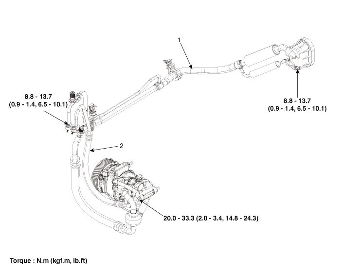
| 1. Suction & Liquid tube assembly
|
2. Discharge hose |
Repair procedures
| Replacement |
| 1. |
If the compressor is marginally operable, run the engine at idle speed, and let the air conditioning work for a few minutes, then shut the engine off. |
| 2. |
Disconnect the negative (-) battery terminal. |
| 3. |
Recover the refrigerant with a recovery / charging station. |
| 4. |
Remove the engine mounting support bracket. G 2.0 NU MPI (Refer to Engine Mechanical System - "Engine Mounting") G 2.5 GDI THETA II (Refer to Engine Mechanical System - "Engine Mounting") |
| 5. |
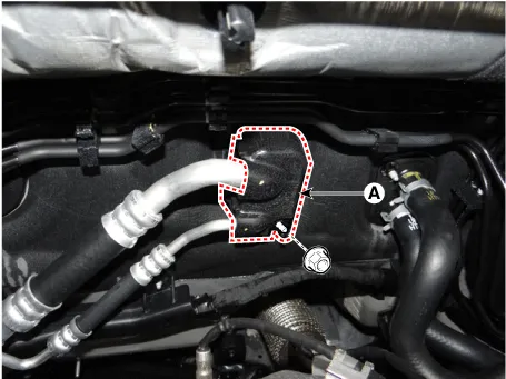
Loosen the mounting nut and remove the expansion valve cover (A).
|
| 6. |
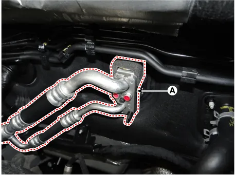
Remove the bolts and the expansion valve (A) from the evaporator core.
|

| 7. |
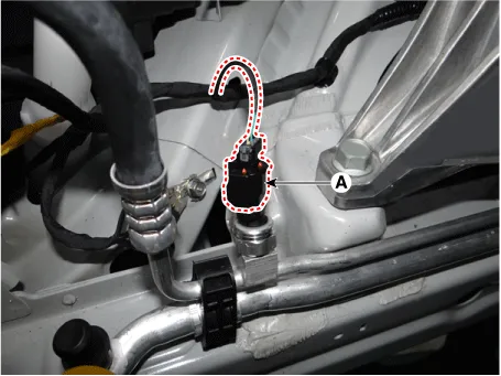
Press the lock pin and separate the A/C pressure transducer connector (A).
|
| 8. |
Loosen the mounting nuts, remove the suction line (A) and discharge line (B).
|
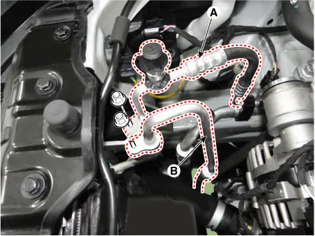
| 9. |
Remove the engine room under cover. G 2.0 NU MPI (Refer to Engine Mechanical System - "Engine Cover") G 2.5 GDI THETA II (Refer to Engine Mechanical System - "Engine Cover") |
| 10. |
Remove the bolts, then disconnect the suction line (A) and discharge line (B) from the compressor.
|

| 11. |
Remove the suction & liquid tube assembly (A) to the upper of engine room.
|
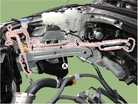
| 12. |
To install, reverse the removal procedure.
|
Repair procedures Oil Specification 1. The HFC-134a system requires synthetic (PAG) compressor oil whereas the R-12 system requires mineral compressor oil.
Description and operation Description The compressor is the power unit of the A/C system. It is located on the side of engine block and driven by a V-belt of the engine.
Other information:
Kia Optima DL3 2019-2026 Service and Repair Manual: Headlamps
Components and components location Component Location 1. Low beam 2. High beam 3. Daytime Running Light / Position lamp 4. Low assist beam 5. Turn signal lamp Schematic diagrams Connector and Terminal Function Connector Terminal Function
Kia Optima DL3 2019-2026 Service and Repair Manual: Multifunction Switch
Specifications Specifications Items Specifications Rated voltage Front fog lamp switch 5 V Lighting Auto lighting Dimmer & Passing Turn signal lamp Wiper Was
Categories
- Manuals Home
- Kia Optima Owners Manual
- Kia Optima Service Manual
- Engine Control / Fuel System
- Emergency trunk safety release
- Automatic Transaxle System
- New on site
- Most important about car
