Kia Optima DL3: Smart Key System / Smart Key Unit
Schematic diagrams
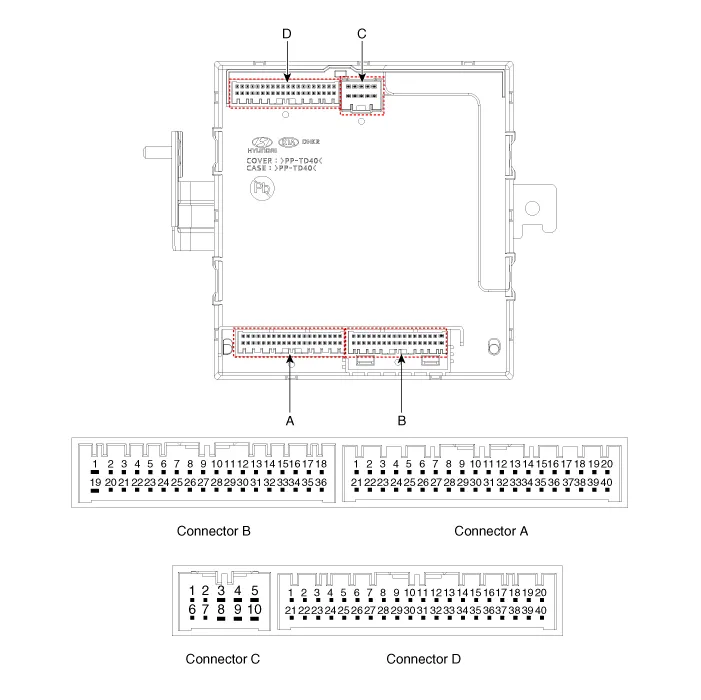
| Connector and Terminal Function |
|
Pin |
Function |
|||
|
Connector A |
Connector B |
Connector C |
Connector D |
|
|
1 |
- |
Front washer switch (Output) |
- |
Driver outside handle switch (Input) |
|
2 |
Rear seat belt indicator_Left (Output) |
- |
ESCL Enable (Output) |
Assist outside handle switch (Input) |
|
3 |
- |
- |
ESCL - (Output) |
- |
|
4 |
- |
- |
- |
- |
|
5 |
External buzzer (Output) |
- |
- |
RPM (Input) |
|
6 |
Rear seat belt indicator_Center (Output) |
Wiper parking switch (Input) |
- |
SSB symbol illumination (+) (Output) |
|
7 |
Puddle pocket lamp (Output) |
- |
ESCL Unlock switch (Input) |
ACC relay (Output) |
|
8 |
Rear seat belt indicator_Right (Output) |
Brake switch (Input) |
- |
IGN1 relay (Output) |
|
9 |
- |
- |
- |
IGN2 relay (Output) |
|
10 |
Headlamp high switch (Input) |
Front wiper volume switch (Input) |
ESCL + (Output) |
Starter relay (Output) |
|
11 |
- |
- |
|
Assist outside handle antenna (+) (Output) |
|
12 |
- |
LIN4 (Safety ECU) |
Interior antenna 2 (+) (Output) |
|
|
13 |
Rear view switch (Input) |
PAS Option (Input) |
Trunk interior antenna 3 (+) (Output) |
|
|
14 |
- |
- |
Interior antenna 1 (+) (Output) |
|
|
15 |
RPAS Power (Output) |
B-CAN (Low) |
Bumper antenna (+) (Output) |
|
|
16 |
FRAS Power (Output) |
B-CAN (High) |
Driver outside handle antenna (+) (Output) |
|
|
17 |
PAS/RPAS Power (Input) |
- |
- |
|
|
18 |
- |
Ground (Power) |
- |
|
|
19 |
- |
- |
- |
|
|
20 |
Ground (ECU) |
Immobilizer power (Output) |
- |
|
|
21 |
- |
Immobilizer ground (Output) |
SSB switch 1 (Input) |
|
|
22 |
K-Line_Immobilizer |
- |
SSB switch 2 (Input) |
|
|
23 |
- |
PAS/RPAS Switch indicator (Output) |
Clutch IGN lock switch |
|
|
24 |
- |
Front wiper switch (Input) |
ESCL COM |
|
|
25 |
Sunroof status (Input) |
- |
Wheel speed sensor (Input) |
|
|
26 |
PAS/RPAS Switch (Input) |
Multifunction switch ground (Input) |
- |
|
|
27 |
ATM Solenoid (Output) |
Wiper power relay (Output) |
- |
|
|
28 |
LIN3 (Rain sensor) |
Auto light sensor ground (Output) |
- |
|
|
29 |
LIN2 (ROA) |
Auto light sensor signal (Input) |
- |
|
|
30 |
LIN1 (PDW-F or PDW-R) |
Auto light sensor power (Output) |
Start feed back (Input) |
|
|
31 |
Door unlock signal (For IFU) EMS (Output) |
- |
Assist outside handle antenna (-) (Output) |
|
|
32 |
Light switch (Input) |
Front wiper high relay (Output) |
Interior antenna 2 (-) (Output) |
|
|
33 |
Fog switch (Input) |
Front wiper low relay (Output) |
Trunk interior antenna 3 (-) (Output) |
|
|
34 |
IGN2 (Input) |
Front wiper low backup switch (Input) |
Interior antenna 1 (-) (Output) |
|
|
35 |
IGN1 (Input) |
P-CAN (Low) |
Bumper antenna (-) (Output) |
|
|
36 |
ACC (Input) |
P-CAN (High) |
Driver outside handle antenna (-) (Output) |
|
|
37 |
Battery + (ECU) |
|
- |
|
|
38 |
Battery + (Power) |
- |
||
|
39 |
- |
- |
||
|
40 |
Front heated nozzle (Output) |
'P' Position (input) |
||
Repair procedures
| Removal |
Integrated Body control Unit (IBU)
| 1. |
Remove the IBU. (Refer to Body Electrical System - "Integrated Body Control Unit") |
Door Outside Handle
| 1. |
Remove the front door outside handle. (Refer to Body - "Front Door Outside Handle") |
Trunk Open Switch
| 1. |
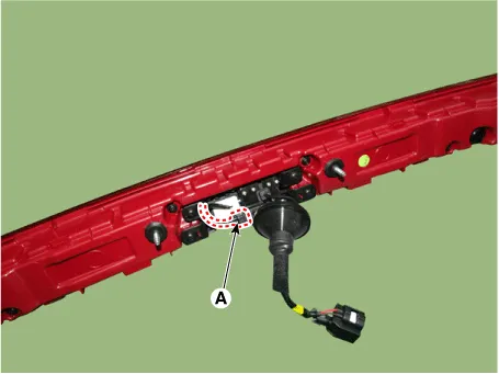
Remove the center rear combination lamp. (Refer to Lighting System - "Rear Combination Lamp") |
| 2. |
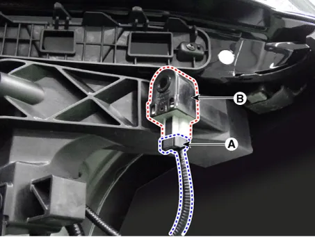
Disconnect the trunk open switch connector (A).
|
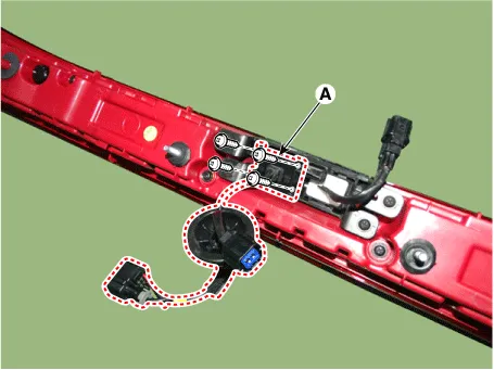
| 3. |
Remove the rear view camera (A) by loosening the mounting screws.
|
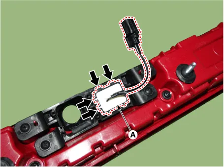
| 4. |
Remove the trunk open switch (A) by pressing the hooks.
|
Buzzer
| 1. |
Disconnect the negative battery terminal. |
| 2. |
Remove the front bumper assembly. (Refer to Body - "Front Bumper assembly") |
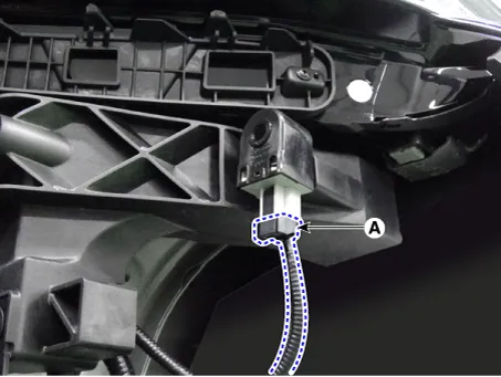
| 3. |
Remove the buzzer (B) after disconnecting the connector (A).
|
| Installation |
| 1. |
Install in the reverse order of removal. |
| Inspection |
Integrated Body control Unit (IBU)
| 1. |
Inspect the IBU by using the KDS. (Refer to Smart Key System - "Smart Key Diagnostic") |
Door Outside Handle
| 1. |
Remove the front door outside handle. (Refer to Body - "Front Door Outside Handle") |
| 2. |
Disconnect the front door outside handle connector and then check for continuity between terminals No 3 and No 6.
|
Trunk Open Switch
| 1. |
Disconnect the negative battery terminal. |
| 2. |
Remove the trunk lid trim. (Refer to Body - "Trunk Lid Trim") |
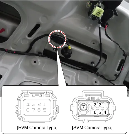
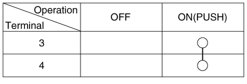
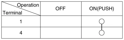
| 3. |
Check for continuity between the terminals.
[RVM Camera Type]
[SVM Camera Type]
|
Buzzer
| 1. |
Disconnect the negative battery terminal. |
| 2. |
Remove the front bumper assembly. (Refer to Body - "Front Bumper assembly") |
| 3. |
Disconnect the buzzer connector (A). |
| 4. |
Test the buzzer by connecting battery power to the terminal 2 and ground the terminal 1.
|
Repair procedures Adjustment Smart Key Code Saving 1. Connect the VCI II in driver side crash pad lower panel, turn the power on KDS.
Repair procedures Removal Interior Antenna 1 1. Disconnect the negative battery terminal. 2. Remove the surround view monitor (SVM) unit.
Other information:
Kia Optima DL3 2019-2026 Service and Repair Manual: Panorama Sunroof
C
Kia Optima DL3 2019-2026 Service and Repair Manual: Blower Unit
Components and components location Component Location 1. Blower unit assembly Components 1. Intake actuator 2. Cluster ionizer 3. Air filter 4. Blower motor assembly 5.
Categories
- Manuals Home
- Kia Optima Owners Manual
- Kia Optima Service Manual
- Body (Interior and Exterior)
- Brake System
- Suspension System
- New on site
- Most important about car
