Kia Optima DL3: ESC (Electronic Stability Control) System / Rear Wheel Speed Sensor
Components and components location
| Components |
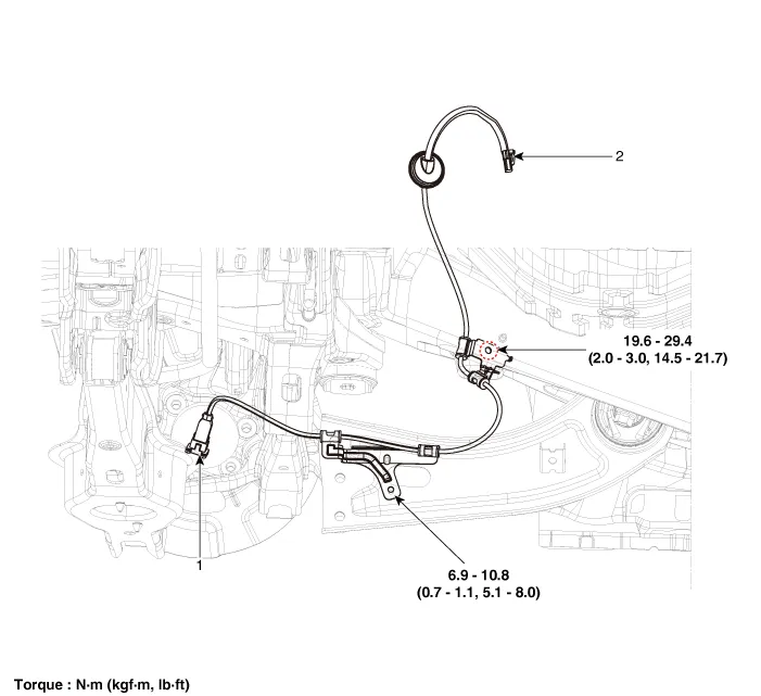
| 1. Rear wheel speed sensor
|
2. Rear wheel speed sensor connector
|
Repair procedures
| Removal |
| 1. |
Disconnect the (-) battery terminal. |
| 2. |
Remove the rear wheel and tire. (Refer to Suspension System - "Wheel") |
| 3. |
Remove the rear brake disc. (Refer to Brake System - "Rear Brake Disc") |
| 4. |
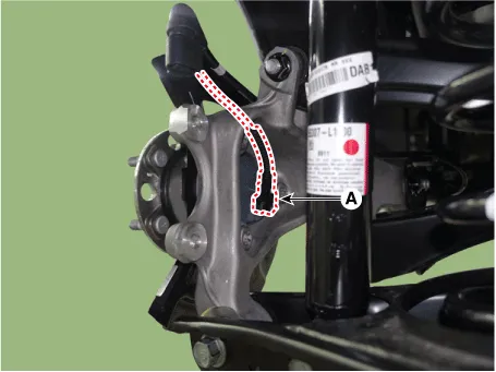
Disconnect the rear wheel speed sensor connector (A).
|
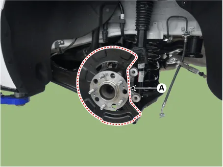
| 5. |
Remove the hub assembly and dust cover (A) after loosening the mounting bolts.
|

| Replacement |
Rear Wheel Speed Sensor Cap
| 1. |
Remove the rear wheel hub bearing assembly. (Refer to Driveshaft and axle - "Rear Axle Assembly") |
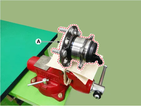
| 2. |
Fix the rear hub bearing assembly (A) on the vise.
|
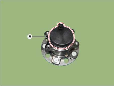
| 3. |
Check the direction of the sensor cap (A).
|

| 4. |
Remove the sensor cap by hammering on a gap between sensor cap and hub bearing assembly using a scraper (A).
|


| 5. |
Check for distortion of damage of the tone wheel or encoder (A).
|


| 6. |
Position the sensor cap to the same direction of sensor cap connector (A) as you checked before removing.
|
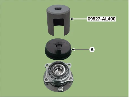
| 7. |
Install the sensor cap (A) with the special service tool (09527-AL400).
|

| 8. |
Install the rear wheel hub bearing assembly. (Refer to Driveshaft and axle - "Rear Axle Assembly") |
| Inspection |
| 1. |
Measure the output voltage between the terminal of the wheel speed sensor and the body ground.
|

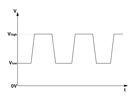
| 2. |
Compare the change of the output voltage of the wheel speed sensor to the normal change of the output voltage as shown below.
V_low : 0.59V - 0.84V V_high : 1.18V - 1.68V Frequency range : 1 - 2,500 Hz |
| Installation |
| 1. |
Install in the reverse order of removal. |
Components and components location Components 1. Front wheel speed sensor 2. Front wheel speed sensor connector Repair procedures Removal and Installation 1.
Description and operation Description Introduction of quick brake warning system (ESS) In case of quick brake by driver, the brake lamp or turn signal is blinked to warn against the vehicle at rear.
Other information:
Kia Optima DL3 2019-2026 Service and Repair Manual: Cluster Ionizer
Components and components location Components Location 1. Condenser Description and operation Description The cluster ionizer makes disinfection and decomposition of bad smell from the air-conditioner or inflow air.
Kia Optima DL3 2019-2026 Service and Repair Manual: Mode Control Actuator
Components and components location Components Location 1. Mode control actuator Description and operation Description The mode control actuator is located at the heater unit. It adjusts the position of the mode door by operating the mode control actuator based on the signal of the A/C co
Categories
- Manuals Home
- Kia Optima Owners Manual
- Kia Optima Service Manual
- Steering System
- Front Axle Assembly
- Suspension System
- New on site
- Most important about car
