Kia Optima DL3: Seat Electrical / Relaxion Comfort Seat
Components and components location
| Component Location |
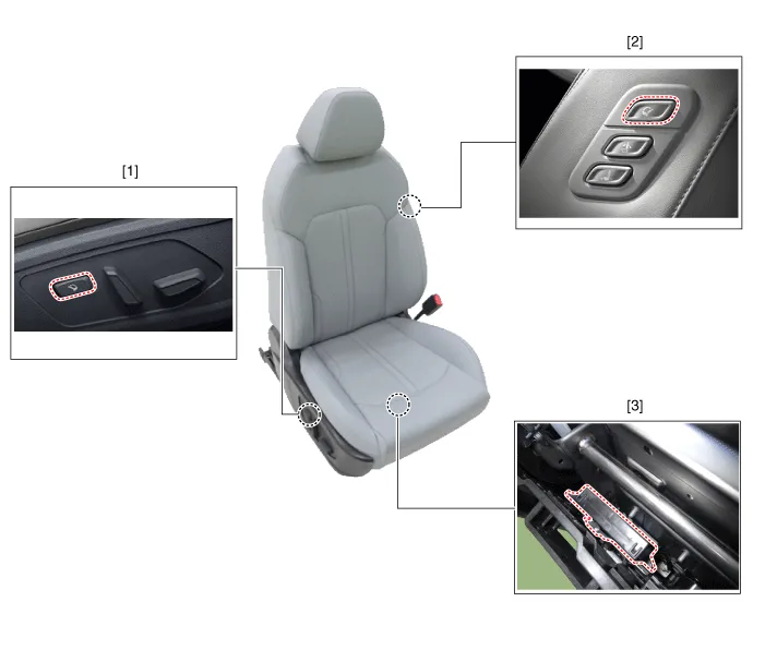
| 1. Relaxion comfort switch
2. Walk-in switch |
3. Relaxion comfort seat unit
(RCSU) |
Schematic diagrams
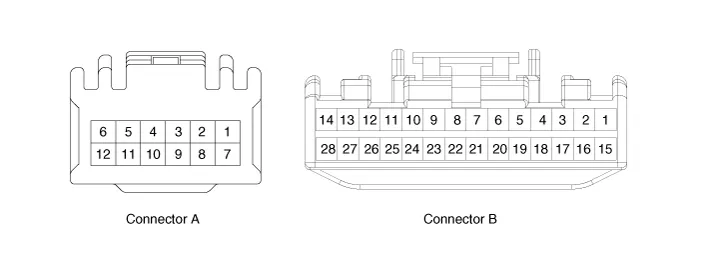
| Connector and Terminal Function |
|
Pin |
Function |
|
|
Connector A |
Connector B |
|
|
1 |
Battery (+) |
Slide motor switch (Forward) |
|
2 |
Slide motor (Forward) |
Slide motor switch (Backward) |
|
3 |
Slide motor (Backward) |
Relaxion comfort switch (Forward) |
|
4 |
Recline motor (Forward) |
Relaxion comfort switch (Backward) |
|
5 |
Recline motor (Backward) |
Rear height motor switch (Up) |
|
6 |
Ground |
Rear height motor switch (Down) |
|
7 |
Battery (+) |
Relaxion comfort switch |
|
8 |
- |
Return switch |
|
9 |
Rear height motor (Up) |
- |
|
10 |
Rear height motor (Down) |
- |
|
11 |
- |
Sensor power |
|
12 |
Ground |
IGN2 |
|
13 |
|
IGN1 |
|
14 |
ECU (Battery +) |
|
|
15 |
Walk-in switch Slide (Forward) |
|
|
16 |
Walk-in switch Slide (Backward) |
|
|
17 |
Walk-in switch Recline (Forward) |
|
|
18 |
Walk-in switch Recline (Backward) |
|
|
19 |
Walk-in relaxion comfort switch |
|
|
20 |
Walk-in return switch |
|
|
21 |
ECU (Ground) |
|
|
22 |
- |
|
|
23 |
- |
|
|
24 |
Limit set power |
|
|
25 |
Slide motor sensor |
|
|
26 |
Recline motor sensor |
|
|
27 |
Rear height motor sensor |
|
|
28 |
Virtual limit set switch |
|
Repair procedures
| Removal |
Walk-in Switch
| 1. |
Remove the walk-in switch. (Refer to Seat Electrical - "Walk-in Switch") |
Relaxion Comfort Switch
| 1. |
Remove the relaxion comfort switch. (Refer to Seat Electrical - "Power Seat Control Switch") |
Relaxion Comfort Seat Unit (RCSU)
| 1. |
Disconnect the negative battery terminal. |
| 2. |
Remove the front passenger seat assembly. (Refer to Body - "Front Seat Assembly") |
| 3. |
Loosen the occupant detection sensor mounting screws (A).
|
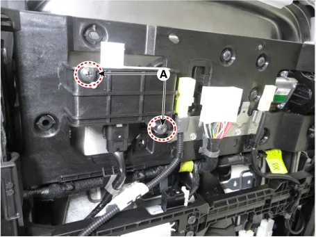
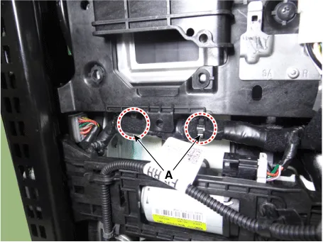
| 4. |
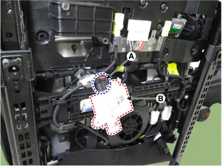
Remove the occupant detection sensor (B) by disconnecting the connector (A).
|
| 5. |
Disconnect the side airbag connector (B) by removing the fixing clip (A).
|
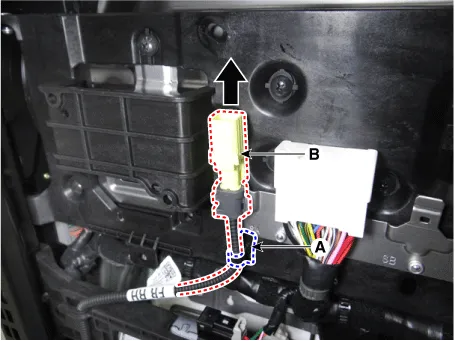
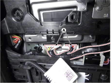
| 6. |
Remove the relaxion comfort seat unit fixing clips (A).
|
| 7. |
Disconnect the relaxion comfort seat unit connectors (A).
|
| 8. |
Loosen the relaxion comfort seat unit mounting screws (A).
|
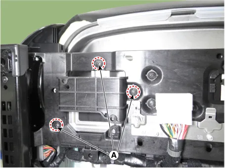
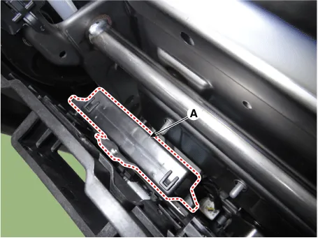
| 9. |
Remove the relaxion comfort seat unit (A).
|
| Installation |
| 1. |
Install in the reverse order of removal. |
Components and components location Component Location 1. Walk-in switch Repair procedures Removal When prying with a flat-tip screwdriver or use a prying trim tool, wrap it with protective tape, and apply protective tape around the related parts, to prevent damage.
Specifications Specifications Smart Key Unit Items Specification Rated voltage DC 12 V Operation voltage DC 9 - 16 V Operation temperature -40 to 185°F (-40 to 85°C) RF Receiver Items Specification Frequency 433.
Other information:
Kia Optima DL3 2019-2026 Service and Repair Manual: Panorama Sunroof Switch
Schematic diagrams Connector and Terminal Function Repair procedures Inspection 1. Remove the overhead console lamp. (Refer to Lighting System - "Overhead Console Lamp") 2. Check for continuity between the terminals in each switch position according to the table
Kia Optima DL3 2019-2026 Service and Repair Manual: Rear Glass Defogger Printed Heater
Repair procedures Inspection • Wrap tin foil around the end of the voltmeter test lead to prevent damaging the heater line. Apply pressure on the tin foil with hand and move the tin foil along the grid line to check for open circ
Categories
- Manuals Home
- Kia Optima Owners Manual
- Kia Optima Service Manual
- Identification Numbers
- Automatic Transaxle System
- Floor Console Assembly
- New on site
- Most important about car
