Kia Optima DL3: Body Electrical System / Smart Key System
Specifications
| Specifications |
Smart Key Unit
|
Items |
Specification |
|
Rated voltage |
DC 12 V |
|
Operation voltage |
DC 9 - 16 V |
|
Operation temperature |
-40 to 185°F (-40 to 85°C) |
RF Receiver
|
Items |
Specification |
|
Frequency |
433.92 MHz |
|
Antenna type |
FSK |
Smart Key
|
Items |
Specification |
||||||||
|
Battery |
Lithium battery 3V 1 unit |
||||||||
|
Distance |
- The distance over which Radio Frequency (RF) Receiver can receive a FOB
transmission signal : 30m - The distance over which Low Frequency (LF) antenna(Outer Handle/ Tailgate ) can detect FOB : 0.7m |
||||||||
|
Battery life |
More than 2 years (10 times / a day)
|
||||||||
|
Push buttons |
4 (Door lock / unlock, Trunk open, Remote start) |
||||||||
|
Frequency (Rx) |
125 kHz |
||||||||
|
Frequency (Tx) |
433.92 MHz |
||||||||
|
Numbers |
2 units |

Antenna
|
Items |
Specification |
|
Rated voltage |
DC 12 V |
|
Operating voltage |
DC 9 - 16 V |
|
Operation temperature |
-22 to 176°F (-30 to 80°C) |
|
Frequency |
125kHz |
|
Numbers |
Interior (3 units), Door (2 units), Front bumper beam (1 unit), Rear bumper
(1 unit) |
Components and components location
| Components (1) |
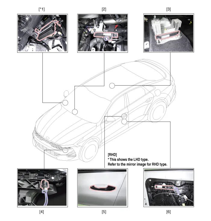
| 1. Integrated body control unit
(IBU) 2. Interior antenna 1 3. Interior antenna 2 |
4. Buzzer 5. Door handle & door antenna 6. Front door antenna |
| Components (2) |
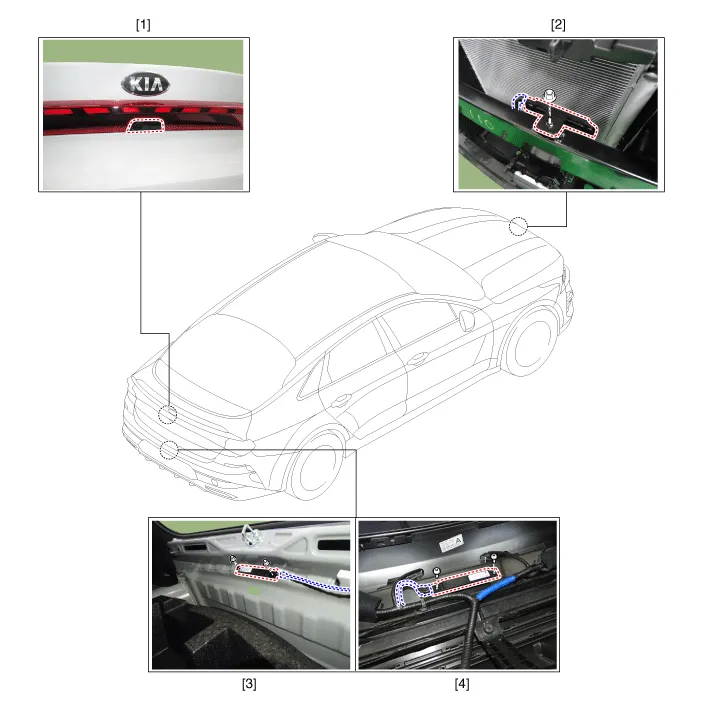
| 1. Trunk open switch 2. Front antenna |
3. Interior antenna 3 4. Exterior bumper antenna |
Components and components location Component Location 1. Relaxion comfort switch 2. Walk-in switch 3. Relaxion comfort seat unit (RCSU) Schematic diagrams Connector and Terminal Function Pin Function Connector A Connector B 1 Battery (+) Slide motor switch (Forward) 2 Slide motor (Forward) Slide motor switch (Backward) 3 Slide motor (Backward) Relaxion comfort switch (Forward) 4 Recline motor (Forward) Relaxion comfort switch (Backward) 5 Recline motor (Backward) Rear height motor switch (Up) 6 Ground Rear height motor switch (Down) 7 Battery (+) Relaxion comfort switch 8 - Return switch 9 Rear height motor (Up) - 10 Rear height motor (Down) - 11 - Sensor power 12 Ground IGN2 13 IGN1 14 ECU (Battery +) 15 Walk-in switch Slide (Forward) 16 Walk-in switch Slide (Backward) 17 Walk-in switch Recline (Forward) 18 Walk-in switch Recline (Backward) 19 Walk-in relaxion comfort switch 20 Walk-in return switch 21 ECU (Ground) 22 - 23 - 24 Limit set power 25 Slide motor sensor 26 Recline motor sensor 27 Rear height motor sensor 28 Virtual limit set switch Repair procedures Removal Walk-in Switch 1.
Repair procedures Adjustment Smart Key Code Saving 1. Connect the VCI II in driver side crash pad lower panel, turn the power on KDS.
Other information:
Kia Optima DL3 2019-2026 Service and Repair Manual: Rheostat
Schematic diagrams Connector and Terminal Function Repair procedures Removal 1. Disconnect the negative battery terminal. 2. Remove the crash pad lower panel. (Refer to Body - "Crash Pad Lower Panel") 3.
Kia Optima DL3 2019-2026 Service and Repair Manual: Walk-in Switch
Components and components location Component Location 1. Walk-in switch Repair procedures Removal When prying with a flat-tip screwdriver or use a prying trim tool, wrap it with protective tape, and apply prote
Categories
- Manuals Home
- Kia Optima Owners Manual
- Kia Optima Service Manual
- Timing Chain
- Steering System
- Battery
- New on site
- Most important about car
