Kia Optima DL3: Brake System / Master Cylinder
Components and components location
| Components |
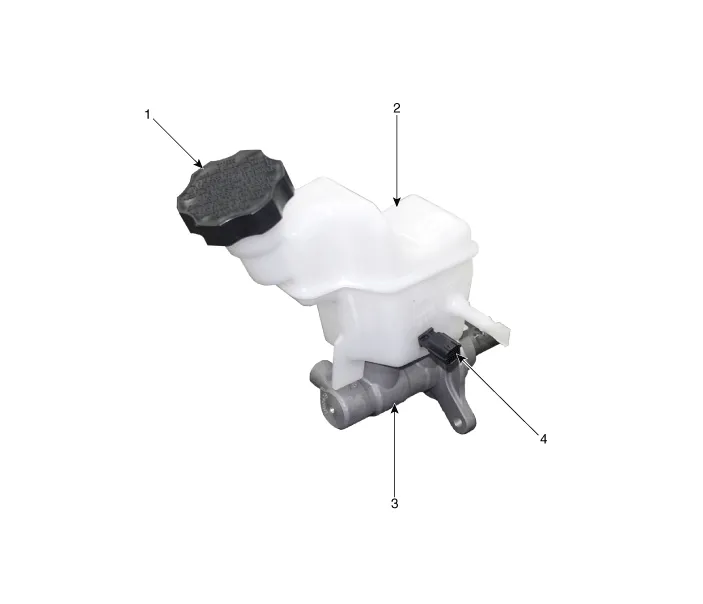
| 1. Reservoir cap 2. Reservoir |
3. Master cylinder 4. Brake fluid level sensor |
Repair procedures
| Removal |
| 1. |
Turn ignition switch OFF and disconnect the negative (-) battery cable. |
| 2. |
Remove the air cleaner assembly. G 2.0 NU MPI (Refer to Engine Mechanical System - "Air Cleaner") G 2.5 GDI THETA II (Refer to Engine Mechanical System - "Air Cleaner") |
| 3. |
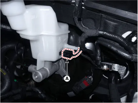
Disconnect the brake fluid level sensor connector (A).
|

| 4. |
Remove the brake fluid from the master cylinder reservoir with a syringe.
|
| 5. |
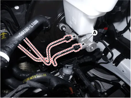
Separate the brake tube (A) from the master cylinder by loosening the tube flare nut.
|
| 6. |
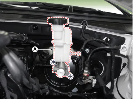
Remove the master cylinder (A) after loosening the master cylinder nuts.
|
| 7. |
Separate the reservoir from the master cylinder after remove the screw (A).
|

| Installation |
| 1. |
Install in the reverse order of removal.
|
| 2. |
After installation, bleed the brake system. (Refer to Brake System - "Brake Bleeding Prcoedures") |
| 3. |
Check the brake oil leakage and pedal operating condition. |
Components and components location Components 1. Reservoir cap 2. Reservoir 3. Master cylinder 4. Brake fluid level sensor 5.
Components and components location Components 1. HECU flare nuts. 2. HECU to body mounting nuts. 3. Master cylinder to HECU flare nut.
Other information:
Kia Optima DL3 2019-2026 Service and Repair Manual: Integrated Memory Seat (IMS) Switch
Schematic diagrams Connector and Terminal Function Repair procedures Removal When prying with a flat-tip screwdriver or use a prying trim tool, wrap it with protective tape, and apply protective tape around the related parts, to prevent dam
Kia Optima DL3 2019-2026 Service and Repair Manual: Vanity Lamp
Repair procedures Removal When removing with a flat-tip screwdriver or remover, wrap protective tape around the tools to prevent damage to components. 1.
Categories
- Manuals Home
- Kia Optima Owners Manual
- Kia Optima Service Manual
- Timing Chain
- Battery
- Floor Console Assembly
- New on site
- Most important about car
