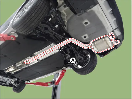
Kia Optima DL3: Intake And Exhaust System / Muffler
Components and components location
| Components |
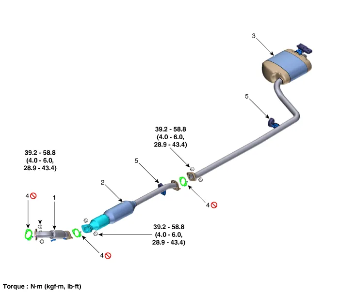
| 1. Front muffler 2. Catalytic converter & Center muffler assembly 3. Rear muffler |
4. Gasket 5. Hanger |
Repair procedures
| Removal and Installation |
Front Muffler
| 1. |
Disconnect the battery negative terminal. |
| 2. |
Remove the engine cover. (Refer to Engine and Transaxle Assembly - "Engine Cover") |
| 3. |
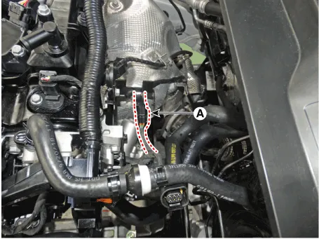
Disconnect the oxygen sensor connector (A) and then separate from bracket..
|
| 4. |
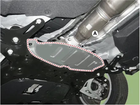
Remove the front muffler heat protector (A).
|
| 5. |
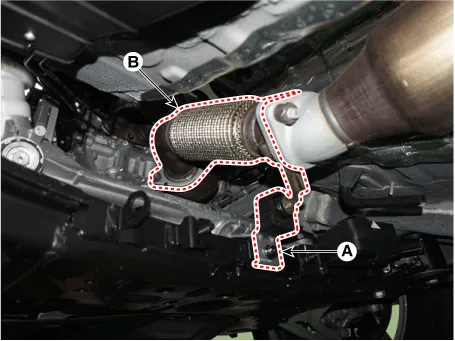
Remove the front muffler.
|
| 6. |
Install in the reverse order of removal.
|
Catalytic Converter & Center Muffler Assembly
| 1. |
Remove the front muffler heat protector (A).
|
| 2. |
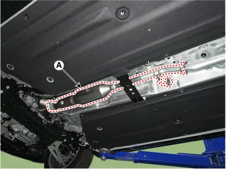
Remove the catalytic converter & center muffler assembly.
|
| 3. |
Install in the reverse order of removal.
|
Rear Muffler
| 1. |
Remove the rear muffler (A).
|
| 2. |
Install in the reverse order of removal.
|
Components and components location Components 1. Heat protector 2. Exhaust manifold gasket 3. Exhaust manifold 4.
Flow diagram Engine Oil Schemetics
Other information:
Kia Optima DL3 2019-2025 Service and Repair Manual: Power Door Mirror Switch
Schematic diagrams Connector and Terminal Function Pin Function 1 B-CAN (Low) 2 B-CAN (High) 3 Ground (Assist safety) 4 Assist safety 5 LIN (For IMS)
Kia Optima DL3 2019-2025 Service and Repair Manual: Condenser
Components and components location Components Location 1. Condenser Repair procedures Inspection 1. Check the condenser fins for clogging and damage. If clogged, clean them with water, and blow them with compressed air.
Categories
- Manuals Home
- Kia Optima Owners Manual
- Kia Optima Service Manual
- Front Axle Assembly
- Power Train
- Features of your vehicle
- New on site
- Most important about car

