
Kia Optima DL3: Lubrication System / Oil Level Gauge & Pipe
Repair procedures
| Removal and Installation |
| 1. |
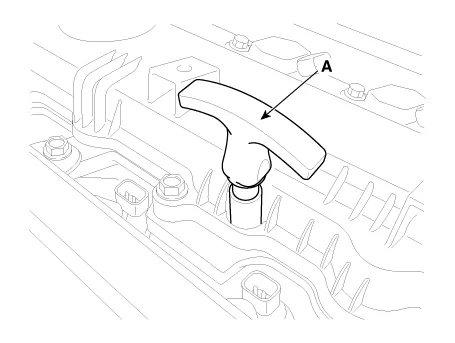
Remove the oil level gauge (A).
|
| 2. |
Install in the reverse order of removal. |
Repair procedures Removal and Installation 1. Disconnect the oil pressure switch connector (A) and then remove the oil pressure switch (B).
Repair procedures Removal and Installation Do not disassemble the oil pump (A) from timing chain cover because it is supplied as timing chain cover & oil pump assembly.
Other information:
Kia Optima DL3 2019-2026 Service and Repair Manual: Power Door Mirrors
C
Kia Optima DL3 2019-2026 Service and Repair Manual: Lumbar Support System
Repair procedures Inspection 1. Remove the front seat back. (Refer to Body - "Front Seat Back Cover") 2. Disconnect the connector (A). 3. When the battery power is supplied to the motor connector, check the motor for smooth operation.
Categories
- Manuals Home
- Kia Optima Owners Manual
- Kia Optima Service Manual
- CVVT Oil Control Valve (OCV)
- Emergency trunk safety release
- Automatic Transaxle System
- New on site
- Most important about car
