Kia Optima DL3: Power Door Locks / Power Door Lock Module
Repair procedures
| Inspection |
When prying with a flat-tip screwdriver or use a prying trim tool, wrap it with protective tape, and apply protective tape around the related parts, to prevent damage. |

Front Door Lock Module
| 1. |
Disconnect the negative battery terminal. |
| 2. |
Remove the front door module. (Refer to Body - "Front Door Module") |
| 3. |
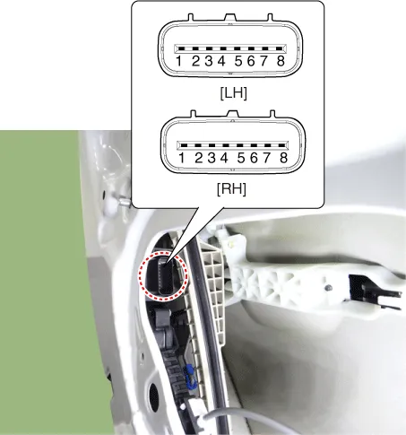
Disconnect the connector from the door lock actuator.
|
|||||||||||||||||||||||||||||
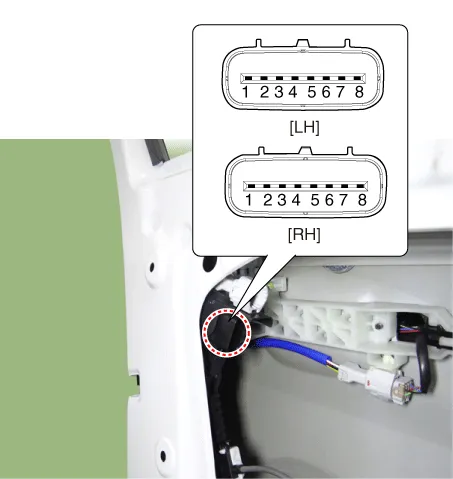
| 4. |
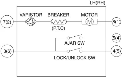
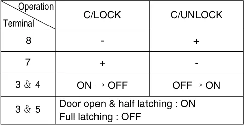
Check actuator operation by connecting power and ground as shown below. To prevent damage to the actuator, apply battery voltage only momentarily.
[LH]
[RH]
|
Rear Door Lock Module
| 1. |
Disconnect the negative battery terminal. |
| 2. |
Remove the rear door module. (Refer to Body - "Rear Door Module") |
| 3. |
Disconnect the connector from the door lock actuator.
|
|||||||||||||||||||||||||||||||||||||||||||||||||||||
| 4. |
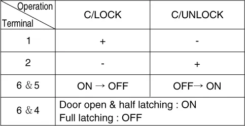
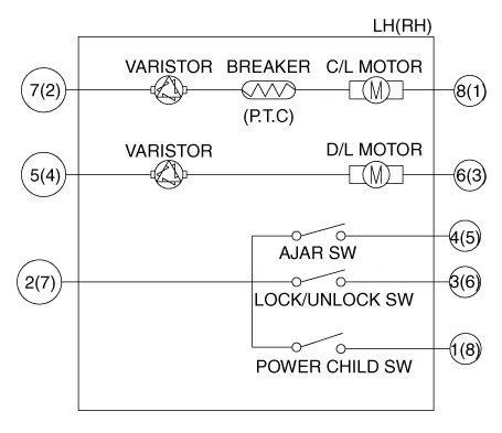
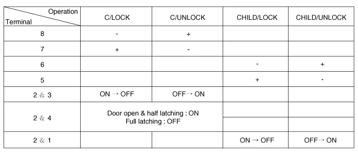
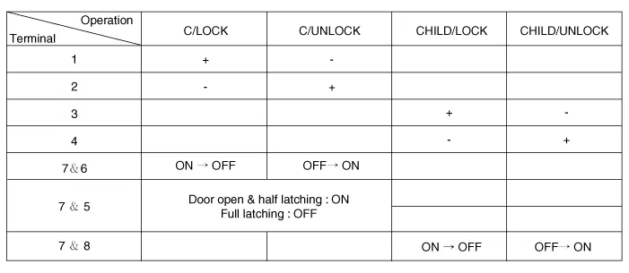
Check actuator operation by connecting power and ground as shown below. To prevent damage to the actuator, apply battery voltage only momentarily. [Central Lock]
[Power Child Lock]
[LH]
[RH]
|

Trunk Lock Module
| 1. |
Disconnect the negative battery terminal. |
| 2. |
Remove the trunk lid trim. (Refer to Body - "Trunk Lid Trim") |
| 3. |
Disconnect the trunk lock module connector (A).
|
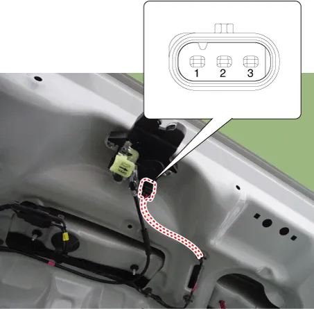
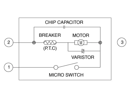
| 4. |
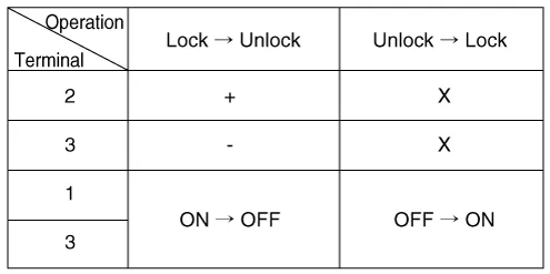
Check actuator operation by connecting power and ground as shown below. To prevent damage to the actuator, apply battery voltage only momentarily.
|
| Removal |
Front Door Lock Module
| 1. |
Remove the front door latch. (Refer to Body - "Front Door Latch") |
Rear Door Lock Module
| 1. |
Remove the rear door latch. (Refer to Body - "Rear Door Latch") |
Trunk Lock Module
| 1. |
Remove the trunk lid latch. (Refer to Body - "Trunk Lid Latch") |
| Installation |
| 1. |
Install in the reverse of the removal. |
Repair procedures Inspection Power Window Main Switch Diagnosis With KDS 1. In the body electrical system, failure can be quickly diagnosed by using the vehicle diagnostic system (KDS).
Components and components location Component Location 1. Power door mirror 2. Power door mirror switch
Other information:
Kia Optima DL3 2019-2026 Service and Repair Manual: Washer Switch
R
Kia Optima DL3 2019-2026 Service and Repair Manual: Evaporator Temperature Sensor
Description and operation Description The evaporator temperature sensor will detect the evaporator core temperature and interrupt compressor relay power in order to prevent evaporator from freezing by excessive cooling. The evaporator temperature sensor has the Negative Temperature Coefficient (NTC).
Categories
- Manuals Home
- Kia Optima Owners Manual
- Kia Optima Service Manual
- Rear Brake Disc
- Lift And Support Points
- Motor Driven Power Steering
- New on site
- Most important about car
