Kia Optima DL3: Body Electrical System / Power Door Mirrors
Components and components location
| Component Location |
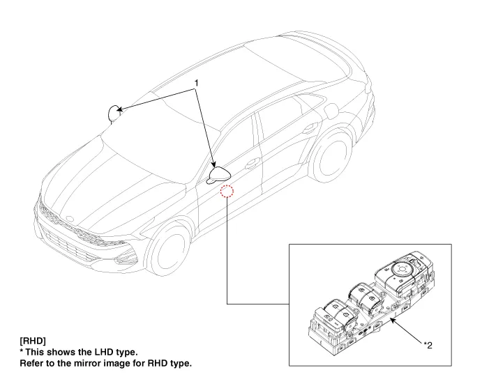
| 1. Power door mirror |
2. Power door mirror switch
|
Repair procedures Inspection When prying with a flat-tip screwdriver or use a prying trim tool, wrap it with protective tape, and apply protective tape around the related parts, to prevent damage.
Schematic diagrams Connector and Terminal Function Pin Function 1 B-CAN (Low) 2 B-CAN (High) 3 Ground (Assist safety) 4 Assist safety 5 LIN (For IMS) 6 Battery (+) 7 IGN1 8 Driver safety 9 IMS Switch (For IMS) / Mirror Common (For Non IMS) 10 Mirror unfolding motor (Non IMS) 11 Mirror folding motor (Non IMS) 12 Mirror horizontal LH (Non IMS) 13 Mirror vertical LH (Non IMS) 14 Mirror vertical RH (Non IMS) 15 Mirror horizontal RH (Non IMS) 16 Ground Repair procedures Inspection Diagnosis With KDS 1.
Other information:
Kia Optima DL3 2019-2026 Service and Repair Manual: Ventilated and Heated Seat Switch
Schematic diagrams Connector and Terminal Function [Front Seat] [Ventilation+Heater Type / Non-Heater Type] Pin Function Pin Function Ventilation+Heater Type Non-Heater Type Ventilation+Heater Type Non-Heater Type
Kia Optima DL3 2019-2026 Service and Repair Manual: Evaporator Core
Repair procedures Replacement 1. Disconnect the negative (-) battery terminal. 2. Remove the heater and blower assembly. (Refer to Heater - "Heater Unit") 3. Loosen the mounting screws, lock pin and remove the evaporator core cover (A).
Categories
- Manuals Home
- Kia Optima Owners Manual
- Kia Optima Service Manual
- Body Electrical System
- Floor Console Assembly
- Battery
- New on site
- Most important about car
