Kia Optima DL3: Body Electrical System / Power Door Locks
Components and components location
| Component Location |
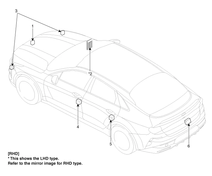
| 1. Hood switch 2. Integrated Body Control Unit (IBU) 3. Horn |
4. Front door actuator & switch
5. Rear door actuator & switch 6. Trunk actuator & switch |
Schematic diagrams Connector and Terminal Function Repair procedures Inspection 1. Disconnect the negative battery terminal.
Repair procedures Inspection Power Window Main Switch Diagnosis With KDS 1. In the body electrical system, failure can be quickly diagnosed by using the vehicle diagnostic system (KDS).
Other information:
Kia Optima DL3 2019-2026 Service and Repair Manual: Power Seat Control Switch
Repair procedures Removal 1. Remove the front seat shield outer cover. (Refer to Body - "Front Seat Shield Outer Cover") 2. Remove the power seat control switch (A) by loosening the mounting screws.
Kia Optima DL3 2019-2026 Service and Repair Manual: Smart Key Unit
Schematic diagrams Connector and Terminal Function Pin Function Connector A Connector B Connector C Connector D 1 - Front washer switch (Output) - Driver outside handle switch (Input)
Categories
- Manuals Home
- Kia Optima Owners Manual
- Kia Optima Service Manual
- Front Axle Assembly
- Timing Chain
- Floor Console Assembly
- New on site
- Most important about car
