
Kia Optima DL3: Seat Electrical / Power Seat Motor
Components and components location
| Components |
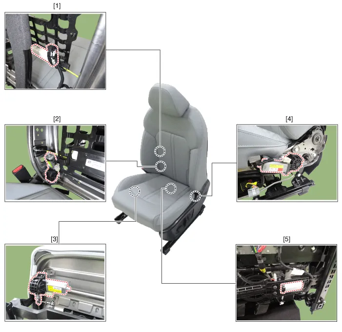
| 1. Lumbar support motor 2. Reclining motor 3. Front height motor |
4. Rear height motor 5. Slide motor |
Repair procedures
| Inspection |
| 1. |
Disconnect the negative battery terminal. |
| 2. |
Disconnect the motor connector after removing the seat. A : Front height motor
B : Slide motor
C : Rear height motor
D : Reclining motor
E : Lumbar support motor
|
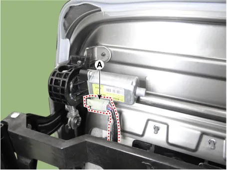
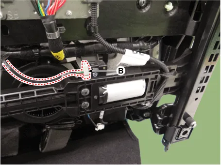
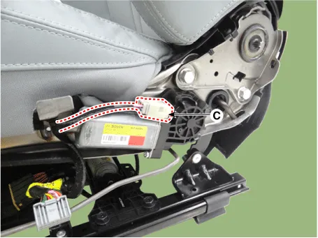
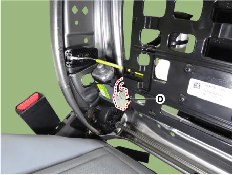
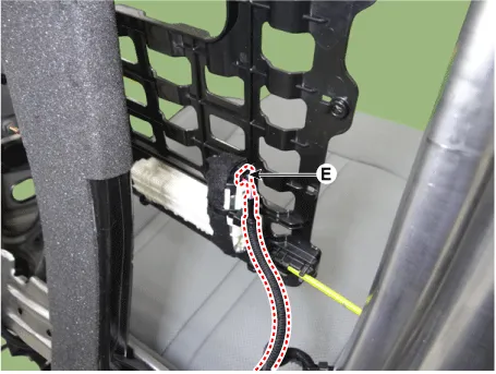
| 3. |
When the battery power is supplied to the motor connector, check the motor for smooth operation.
|
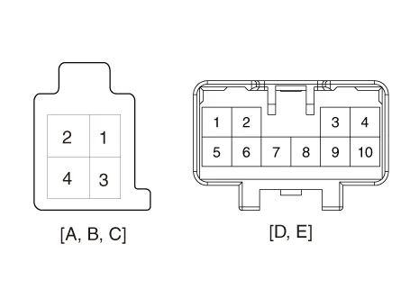
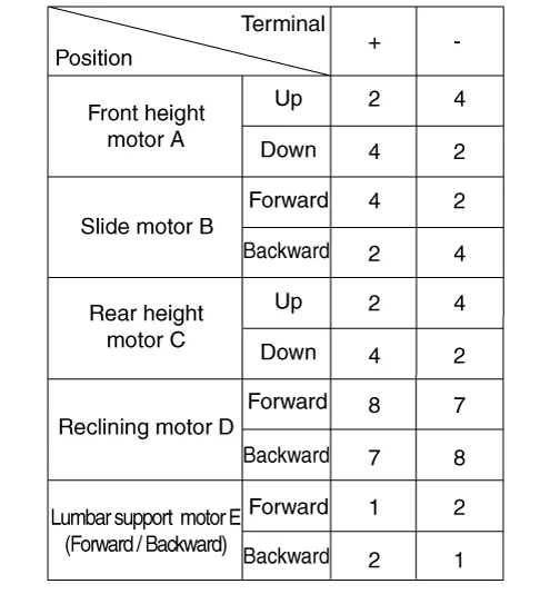
Repair procedures Removal 1. Remove the front seat shield outer cover. (Refer to Body - "Front Seat Shield Outer Cover") 2.
Components and components location Component Location 1. Walk-in switch Repair procedures Removal When prying with a flat-tip screwdriver or use a prying trim tool, wrap it with protective tape, and apply protective tape around the related parts, to prevent damage.
Other information:
Kia Optima DL3 2019-2026 Service and Repair Manual: Fog Lamp
Repair procedures Removal Front Fog Lamp 1. Disconnect the negative battery terminal. 2. Remove the front bumper assembly. (Refer to Body - "Front Bumper Assembly") 3.
Kia Optima DL3 2019-2026 Service and Repair Manual: Auto Defogging Sensor
Description and operation Description The auto defogging sensor is installed on the front window glass. The sensor judges and sends signal if moisture occurs to blow out wind for defogging. The air conditioner control module receives signal from the sensor and restrains moisture and eliminate defog by controlling the intake actu
Categories
- Manuals Home
- Kia Optima Owners Manual
- Kia Optima Service Manual
- Cooling System
- Automatic Transaxle System
- Body Electrical System
- New on site
- Most important about car
